
Introduction
The global thermocouple market was worth about USD 763 million in 2025 and should reach USD 1.11 billion by 2035, expanding near 3.8 percent a year according to Expert Market Research. Plastics processing takes a big slice of that demand, because a single mold can carry 16, 32 or 96 separate sensor points. Among all the sensor families used on those molds, one shows up more than any other: the k type thermocouple.
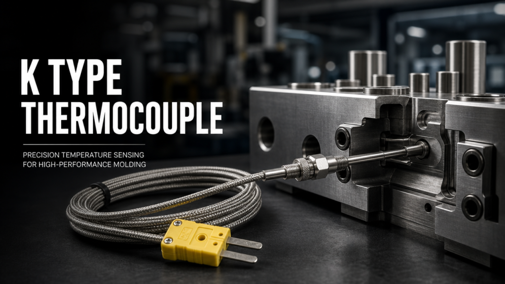
Walk into almost any shop running a hot runner temperature controller and you will find Chromel-Alumel sensors on the manifold, at the nozzles and sometimes on the sprue bushing. A well built hot runner system can carry a dozen of them. They are cheap, they tolerate high heat and most controllers are built around their output curve. A thermocouple works on the Seebeck effect, and type K has been the industrial default for decades.
That familiarity hides a few traps. Range figures quoted on supplier pages rarely match what a mold actually sees. Tolerance classes get mixed up. Wire gets swapped for something that looks identical. This guide covers what matters when you are specifying, replacing or troubleshooting a k type thermocouple on an injection mold, and where a k type thermocouple probe stops being a commodity item.
What a K Type Thermocouple Really Measures
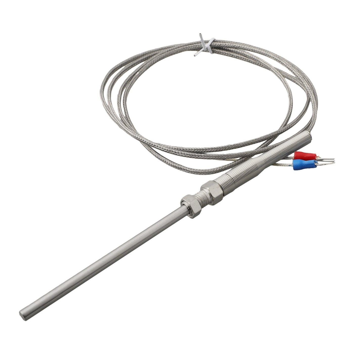
A k type thermocouple is not a thermometer in the usual sense. Two dissimilar metals meet at a junction, a temperature difference across that junction generates a small voltage, and the instrument on the other end works backward from the voltage to a temperature.
A k type thermocouple pairs a nickel-chromium positive leg with a nickel-aluminium negative leg. Materials people call these Chromel and Alumel, though the trade names belong to specific suppliers. The alloy combination was standardised decades ago and it is now the default general purpose sensor in industrial settings, from heat treatment furnaces to exhaust gas measurement.
What makes a k type thermocouple a good fit for molding is the slope of its output. The junction generates roughly 39 to 43 microvolts for every degree Celsius of difference. That signal is small enough to need decent wiring and large enough to survive the electrical noise inside a molding cell. Pair it with a mould temperature controller and the loop closes.
The sensor also has no moving parts and needs no excitation current, unlike a resistance sensor. Nothing to wear out, nothing to drift from supply voltage changes.
Inside the Junction: Alloys, Output and Wire Grades
Three details inside the sensor assembly decide how well a k type thermocouple performs in production, and none of them appear on a price list.
Conductor composition
The positive leg runs about 90 percent nickel with 10 percent chromium. The negative leg is close to 95 percent nickel with aluminium, manganese and silicon added. Because the negative leg contains aluminium it is slightly magnetic, which gives you a quick field test: a magnet sticks to one wire and not the other.
Millivolt output
Output is not perfectly linear. At 100°C the pair produces around 42 microvolts per degree, near 43 at 500°C and about 39 at 1000°C. Controllers store a polynomial or lookup table rather than a straight line, so a k type thermocouple accuracy check done at room temperature says little about how the same k type thermocouple behaves at 300°C. A sensor that reads fine when cold can drift at melt temperature without looking broken.
Thermocouple grade versus extension grade
Type k thermocouple wire comes in two levels, and swapping them is one of the quiet ways a k type thermocouple loses accuracy. Thermocouple grade wire is made to tighter limits and is used to build the sensor itself. Extension grade wire, marked KX, carries the signal from the mold to the controller cabinet. KX wire has a wider tolerance band on purpose, since it sits in a much narrower temperature window.
| Property | Type K value | Notes for mold work |
|---|---|---|
| Positive leg | Nickel-chromium | Non-magnetic |
| Negative leg | Nickel-aluminium | Slightly magnetic |
| Typical output | 39-43 microvolts per °C | Non-linear, stored as a curve |
| Working range | 0°C to 1260°C | Molds run far below this |
| ANSI colour | Yellow positive, red negative | US convention |
| Extension grade | KX | Used for the run back to the cabinet |
| Typical sheath | Stainless steel 304 or Inconel | Inconel for abrasive resins |
Temperature Range in Real Mold Conditions
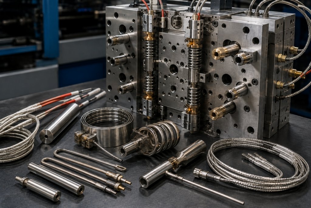
Supplier pages quote 0°C to 1260°C for type K. Useful as that number is, it says little about a molding floor. Engineering resins such as PEEK, PPS and PEI run in the 350°C to 420°C band, well inside the linear part of the curve. Commodity resins sit far lower, often between 200°C and 260°C.
Where the headline k type thermocouple range becomes misleading is at the edges. Above roughly 1000°C the alloy starts to oxidise and the calibration shifts permanently. Below -40°C the standard tolerance no longer applies and materials have to be selected specially.
Practical consequence: the useful k type thermocouple range on a mold is narrow. Zone setpoints on a 96 zone system rarely exceed 450°C. Choose a k type thermocouple whose accuracy is good across that window rather than one that simply survives to 1260°C. Two probes can share identical range figures and still behave very differently at 300°C.
Tolerance Classes and What They Cost You
Two standards cover type K tolerances and they do not agree with each other. ASTM E230 is common in the United States. IEC 60584-1 is used across most of the rest of the world.
Under ASTM E230 a standard limit of error sensor is good to ±2.2°C or 0.75 percent of reading, whichever is greater. Special limits of error tighten that to ±1.1°C or 0.4 percent. Under IEC 60584-1 a Class 1 k type thermocouple holds ±1.5°C up to 375°C and then moves to a percentage formula, while Class 2 allows ±2.5°C over the same stretch.
For a manifold running at 250°C the difference between a standard and a special limit sensor can be a couple of degrees. That sounds trivial until you see it on a thin wall part, where two degrees at the gate changes fill pressure and part weight.
If you are chasing a hot runner controller fault that only shows up on one grade of resin, check the tolerance class before you touch the control settings.
Ordering tip. Ask for the class in writing, and check whether the class applies to the sensor or to the wire inside it. A special limit junction paired with ordinary extension wire loses most of the advantage.
Wire, Connectors and Getting Polarity Right
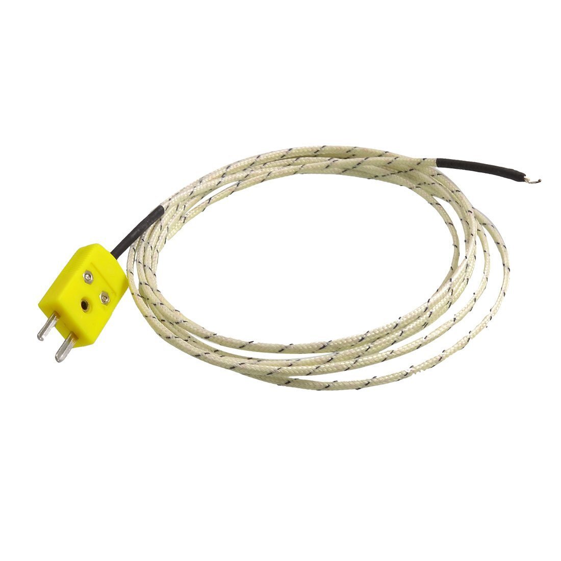
Reversed polarity is the single most common field error, and it produces a reading that wanders rather than fails outright. In the United States the positive conductor of type K is yellow and the negative conductor is red, following ANSI MC96.1. Type k thermocouple wire sold for extension duty carries the same colours plus an X on the type designation, so a spool marked KX is the correct choice for the run back to the cabinet.
Connectors matter more than most people expect. A miniature or standard plug must use type K compensating contacts. Swap in an ordinary brass terminal block and you create a second junction at the screw, which adds an error the controller cannot see or correct. Your hot runner controller accessories order should always specify K type contacts and the matching panel socket.
Shielding is the other half of the job. Route KX wire away from heater power cables where the layout allows. Cross them at right angles when you cannot avoid it. Keep the drain wire grounded at the cabinet end only, never at both ends.
A k type thermocouple probe that arrives pre-terminated saves time at installation and removes one source of error. Bare wire ends twisted around a screw are how most polarity mistakes start.
Grounded or Ungrounded: The Noise Trade-off

The junction inside a mineral insulated probe can touch the sheath or float free of it.
A grounded junction responds fast, because heat reaches the measuring point quickly. It also creates an electrical path between the sensor and the mold, which is where noise enters. An ungrounded junction adds a small thermal delay but breaks that path.
Most mold shops default to ungrounded. It costs a second or two in response time and saves a great deal of grief on zones that share a manifold with high current heater circuits.
There are exceptions. Single zone lab molds and small prototype tools often run fine with grounded sensors, and the faster response helps during setup. Pick based on how much electrical noise your modular hot runner temperature controller has to reject, not on habit.
Sheath material follows the same logic. Stainless steel 304 covers most jobs. Abrasive or corrosive resins justify Inconel, and glass filled materials are easier on a swaged tip than on a long straight probe.
K Type vs J Type on a Hot Runner Controller
Type J turns up often enough that technicians mix the two up. Both are base metal sensors, both are inexpensive, and both appear on molding equipment.
The split comes down to temperature ceiling and signal slope. Type J uses iron and constantan, tops out near 760°C and produces a steeper millivolt curve, so it resolves small changes well at lower temperatures. A k type thermocouple keeps working past 1000°C and survives oxidation better.
Which one a controller expects is not a preference. Input boards are configured for a specific sensor type, and a K input read with a J sensor produces a temperature that is wrong by a wide margin. When you compare a j type vs k type thermocouple on the bench, check the controller setting before you blame the part. That comparison is the first thing to run when a zone reports a number that nobody believes.
| Feature | Type J | Type K |
|---|---|---|
| Conductors | Iron and Constantan | Nickel-chromium and Nickel-aluminium |
| Working range | -210°C to 760°C | -200°C to 1260°C |
| Output slope | Steeper | Flatter |
| Oxidation behaviour | Rusts in damp air | More stable in oxidising atmospheres |
| Typical mold use | Low and medium melt temperatures | General purpose, high temperature zones |
| US colour code | White positive, red negative | Yellow positive, red negative |
| Controller input | Must be set to J | Must be set to K |
Signal Path from Junction to Controller

Understanding the chain helps when a zone misbehaves, because the fault is rarely where it first appears.
Heat reaches the junction. The junction produces a millivolt signal. That signal travels along KX extension wire to the cabinet, where the input board measures the voltage and applies cold junction compensation, since the terminal block itself sits at room temperature rather than at 0°C. The controller converts the corrected voltage into a temperature, compares it against the setpoint and drives heater power through a PID loop.
Every link adds error. A loose terminal, a kinked extension wire or a contaminated junction all show up as the same symptom: a zone that will not hold setpoint. Modern controllers flag an open circuit immediately, but a partially degraded k type thermocouple can sit within the tolerances the controller accepts while still ruining part quality.
Cold junction compensation is the part people forget. If the cabinet fan fails and the inside temperature climbs, every channel shifts at once. That kind of fault looks like a mold problem and is really an electronics room problem.
When the Sensor Is the Problem, Not the Controller
Operators often replace a controller when a reading goes bad. The sensor is more often the culprit, and the signs are fairly consistent. A k type thermocouple that has run for years rarely fails outright, it fades.
| Symptom | What it usually means | Action |
|---|---|---|
| Reading jumps by tens of degrees | Loose or corroded terminal | Re-terminate with K type contacts |
| Zone holds setpoint but parts short shot | Junction reading low, aged sensor | Swap the probe and re-check tolerance |
| Slow response after a setpoint change | Ungrounded junction or aged insulation | Replace, review junction style |
| Sudden open circuit alarm | Broken conductor at the bend radius | Replace probe, check cable routing |
| Two zones disagree on one manifold | Mixed sensor types or grades | Confirm both are K and the same class |
One cheap habit pays off. Keep a known good probe on the bench, and compare any suspect k type thermocouple probe against it at a fixed temperature. Twenty minutes of testing beats a day of swapping parts.
Matching a Sensor to a Controller
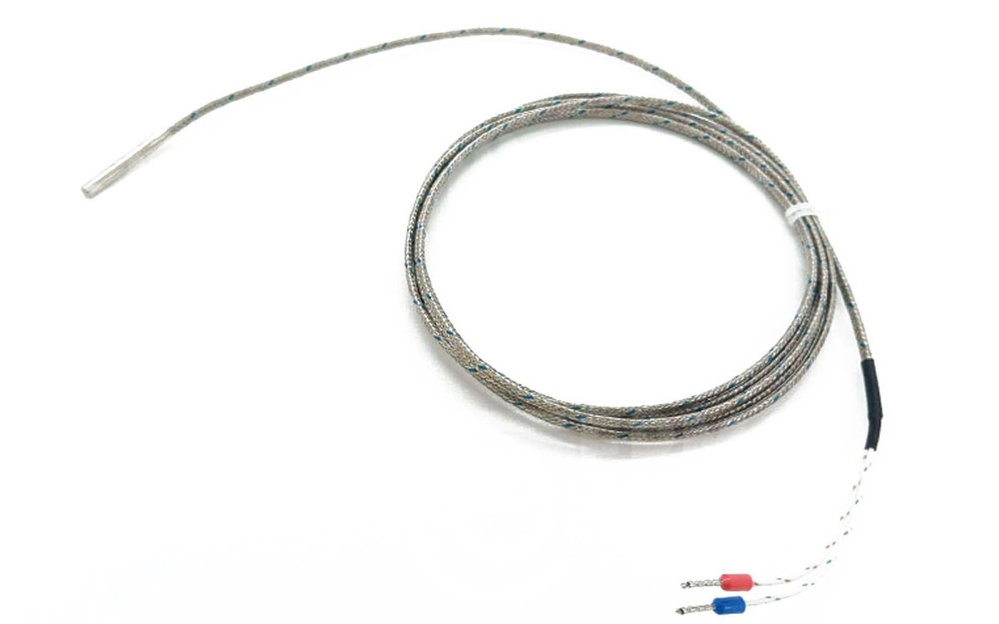
Sensor and controller are a matched pair, and the matching happens on four points. Sensor type has to match the input configuration. Thermocouple grade or extension grade has to suit the location. Connector style has to match the panel socket. Cable length and sheath material have to survive the routing and the resin.
Zone count drives the rest. A 16 zone manifold might use twenty k type thermocouple probes once spares are counted. Large tools run past a hundred. When you buy a touch screen hot runner controller for that kind of tool, confirm how many inputs are K dedicated and whether any channels accept J as well.
Spare parts planning deserves a mention too. Probes fail on a schedule of their own, often mid run. Holding two or three spares per mold size is cheaper than a stalled press. Our temperature controller selection guide covers how zone count, voltage and connector requirements come together on a quotation, and the frequently asked questions page handles the alarm codes that come up most often.
Frequently Asked Questions
What temperature range does a k type thermocouple cover?
Commonly quoted as 0°C to 1260°C, with a usable span from about -200°C upward depending on the class. Mold applications sit in a much narrower band, usually between 200°C and 420°C.
How accurate is a k type thermocouple in practice?
Standard limits of error run to ±2.2°C or 0.75 percent of reading under ASTM E230. Special limits tighten that to ±1.1°C or 0.4 percent. Real world k type thermocouple accuracy also depends on extension wire quality and terminal condition.
Is a k type thermocouple probe interchangeable with a J probe?
Not on the same controller input. The two alloys produce different voltage curves, so a mismatched pair reads the wrong temperature. Physically they may fit the same connector, which is exactly why the mix-up happens.
Does it matter which brand I buy?
Less than you might expect, provided the part follows the standard curve. The same logic applies to Omega Engineering type K sensors, which is a common search term among US buyers. A sensor that is electrically faithful to the type K curve will work on a K input regardless of who built it, since the standard defines the output, not the manufacturer name on the box.
What does vary by supplier is the class, the sheath and the termination quality. Those three decide whether the part lasts a year or a decade. Look at the datasheet rather than the label, and compare against the reference tables published by bodies such as Omega.
How often should hot runner thermocouples be replaced?
There is no fixed interval, and any k type thermocouple sold with a service life printed on the box is guessing. Replace on evidence: drifting readings, slow response, repeated alarms or parts that change weight without a process change. Many shops swap probes during annual mold maintenance as cheap insurance.
Can a bad thermocouple damage the heater or the mold?
Indirectly, yes. A sensor reading low drives the heater harder than needed, which shortens heater band life and can degrade resin. A sensor reading high leaves the melt cold and causes short shots and gate freeze off.
Summary
The k type thermocouple earns its place on molding equipment through a combination of cost, durability and a well understood output curve. Most problems around it come from three things: picking a sensor by price rather than by tolerance class, mixing thermocouple grade and extension grade wire, and assuming the controller is at fault when a zone drifts.
Get the type, the class and the wiring right, and the sensor becomes one of the least interesting parts of the mold, which is exactly what you want. If you need help matching k type thermocouple probes to a controller configuration, send us your zone list and connector requirements and we will review the pairing before you order.