
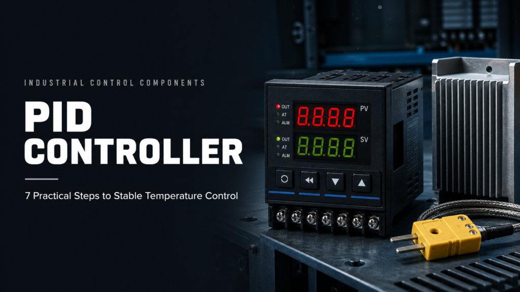
Zone 4 on a 12-zone manifold keeps overshooting. New PID controller. New thermocouple. The heater measures 620 W, close enough to the drawing. So maintenance changes P from 8 to 3, then to 15, then back to 8, and the zone still swings nine degrees either side of setpoint.
Nobody is lying about the parts. The loop is just doing what loops do when one piece of it is late. A PID controller doesn't see the melt. It sees a voltage from a probe that sits somewhere in the steel, and it reacts to that voltage as if it were the whole story.
Here's the short version. Fix the sensor, the output and the wiring first. Tune last. Most "bad controller" calls turn into a loose probe, a reversed thermocouple or a relay that's half dead.
Below are the seven checks we walk through before quoting a controller, plus the wiring and tuning order that keeps a mold running while you sort it out.
Why a PID controller behaves differently on a hot runner zone
Every zone is a small thermal system with its own lag. A nozzle heater might be 300 W. A manifold zone might be 800 W. A valve gate body can pass 1,500 W and still feel sluggish because there's a lot of steel around it.
Power goes in at the heater. Heat travels through the body. The probe picks it up somewhere downstream. That travel time is the problem. Crank the output and the heater wire gets hot first, then the steel, then the sensor. By the time the reading moves, extra energy is already in the metal.
A controller that only looks at the current gap will keep pushing. Then it overshoots. Then it backs off too far. Then it pushes again. That's the swing.
A PID controller uses the recent history of the gap to brake earlier. That's the whole trick. It isn't a smarter thermostat. It's a way to deal with delay.
What P, I and D actually do to a heater
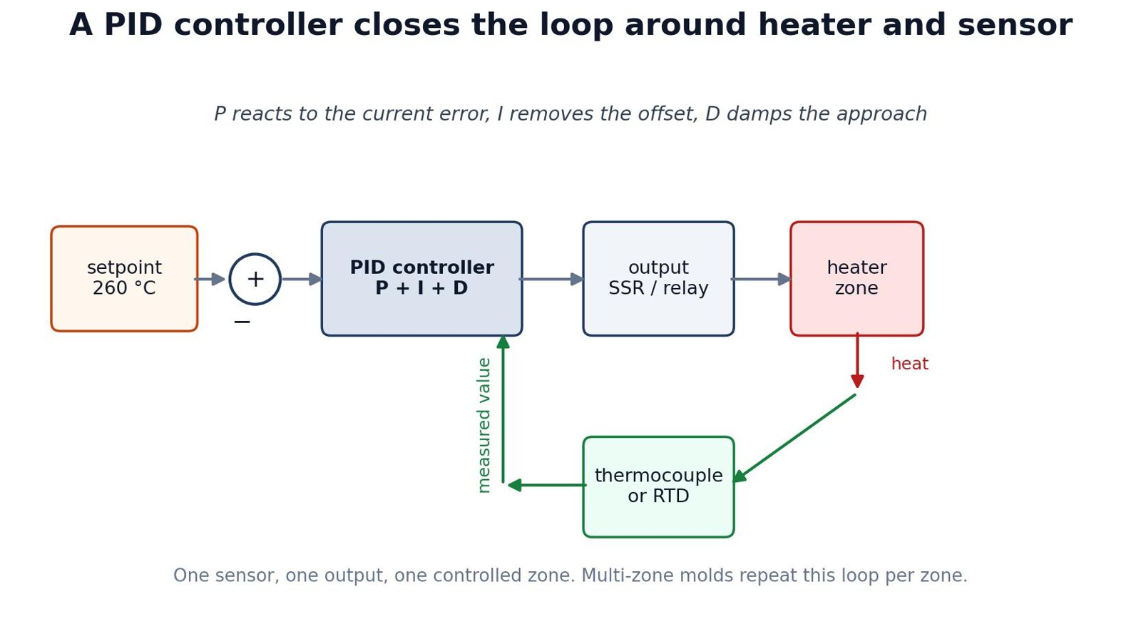
Start with the error. Setpoint 260 °C, reading 250 °C. Error is 10 °C. Everything else is a reaction to that number.
P gives output in proportion to the gap. Big gap, big output. Small gap, small output. Run P by itself and the zone often parks a few degrees below setpoint, because it needs a permanent gap to keep enough power flowing.
I adds up the gap over time. It keeps pushing while the zone sits low, which removes that parking error. Too much I and the zone charges past setpoint, then takes forever to come back. Too little and the last few degrees crawl.
D watches how fast the gap is closing. If the zone is rushing toward setpoint, D cuts output early. Think of it as a brake. On a noisy thermocouple, D also amplifies the noise, which is why a lot of mold shops run PI and leave D low or off.
Same letters everywhere. Different behavior from one box to the next. Sampling rate, output limits and the form of the algorithm all change the result. Copying P, I and D from one machine to another is guesswork, not tuning.
The specifications that change the result
Most buyers start with zone count and price. Fair enough. Those decide whether the cabinet fits the mold. They don't tell you whether the loop will hold.
Look at the input first. A PID controller built for K thermocouples won't read a Pt100 correctly, even if the terminals accept the wire. Check the type and the range. A nozzle at 300 °C is normal. A manifold running engineering resin can go past 400 °C. The box has to be rated for that, not just able to show the number.
Then the output. A relay output is okay for a small heater that clicks a few times a minute. For tight control and frequent switching, you want an SSR drive or a solid state output. Match the output to the relay or contactor you're actually using. A 12 VDC output won't fire a 24 VDC SSR without an interface.
Sampling rate matters more than the display resolution. Ten hertz is common on hot runner controllers and fast enough for most zones. A ±0.1% accuracy claim refers to the controller's own measurement and output, not the whole loop. Sensor error lives outside that number.
| Specification | What to confirm | Why it matters on a mold |
|---|---|---|
| Input type | J or K thermocouple, RTD, selectable | A mismatched input reads the wrong temperature or shows an error |
| Temperature range | Process temperature plus at least 50 °C headroom | Engineering resins and manifolds can exceed standard nozzle ranges |
| Output type | Relay, SSR drive, analog, triac | Determines switching life, control smoothness and wiring |
| Output rating | Current and voltage with margin | An undersized output fails early or welds closed |
| Sampling rate | At least 5–10 Hz for injection molding | Slow sampling adds delay the algorithm cannot correct |
| Alarms | Over-temperature, sensor break, heater break | Turns a silent failure into a maintenance call |
| Communication | Modbus, Ethernet, remote monitoring | Matters when one operator watches many zones |
Seven steps to choose a PID controller
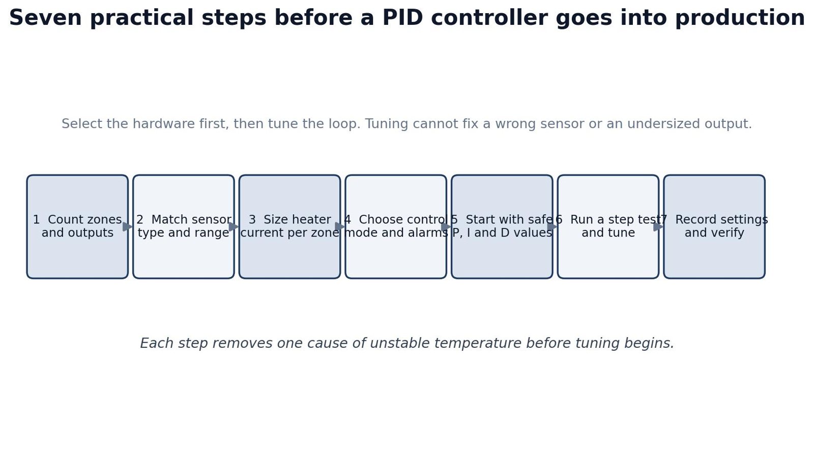
Order matters. Each step removes a failure before you start turning knobs. No controller can fix a sensor in the wrong hole.
One. Count zones and outputs. Count every heater you can control separately. Nozzle tips. Manifolds. Valve gates. Leave spare zones. A modular controller grows one card at a time. A sealed cabinet doesn't.
Two. Match the sensor. Confirm thermocouple type, connector and temperature range. If the mold uses J, buy J, or buy a box that reads both J and K. A new PID controller that reads room temperature on a hot mold is usually on the wrong input type.
Three. Size the output. Watts divided by supply voltage gives current. Add margin for cold starts and low line voltage. A 3,600 W zone at 240 VAC pulls 15 A. The output stage and the wiring should be rated above that, not exactly at it.
Four. Pick the control mode and alarms. PID or PIDD is the baseline for injection molding. Confirm over-temperature, sensor-break and heater-break detection. Those alarms save more parts than another digit on the display.
Five. Start conservative. Don't copy aggressive values from another mold. Start with a modest proportional band, slow integral, D off or low. The first goal is a stable manual response. Speed comes later.
Six. Run a step test. Nudge the setpoint. Watch the response. Change one term at a time. Tune on the mold in the condition you actually run it, not on an empty bench.
Seven. Write it down. Sensor type, output type, P, I, D, alarm limits, mold number. A PID controller that's stable today becomes a mystery next quarter if nobody recorded what changed.
Output power, heat and panel layout
The controller isn't the only hot thing in the cabinet. SSRs, contactors, transformers and wire all dump heat into the same space. Seal that space and the controller drifts, the relay cooks, and nobody can explain why the same settings worked last month.
Give the box its clearance. Don't stack power supplies over a relay bank. Keep thermocouple wire away from heater cable. If they have to share a duct, cross at 90°. Shield the thermocouple cable and ground the shield at one end. Ground both ends and you've built a loop.
For modular controllers, leave space between cards. A card that's cool at 30% output can run much hotter at 90% on a cold mold. Check the panel after a full production day. If the inside of the cabinet is hotter than the PID controller rating, add a fan or move the cabinet. More zones won't fix a heat problem.
Heat is also a hint. A relay that runs hotter than its neighbors, or a terminal that's starting to brown, is telling you the load is higher than expected or the screw is loose. Deal with that before you touch tuning.
One more thing about heat. A PID controller mounted at the top of a cabinet can sit in air that's 10 °C warmer than the air at the bottom. That's enough to shift the controller's own cold-junction compensation, especially on a small panel. Put the controller where the air moves, not above the transformers.
Wiring a PID controller without injecting noise
Most unstable-temperature calls are wiring calls. The PID controller is doing exactly what the signal tells it. The signal is lying.
Use thermocouple extension wire, not copper. Watch polarity. A reversed J or K thermocouple reads a number that looks plausible at room temperature and gets worse as the mold heats. Keep the thermocouple circuit floating unless the manual says otherwise. If the mold and the machine frame sit at different potentials, a ground loop adds noise that looks like a moving temperature.
Run heater power and sensor signal in separate ducts. Cross at right angles when you can't. Use ferrules. Torque the terminals. Put the covers back. A loose terminal adds resistance, heat, and an intermittent fault that takes a day to find.
Label both ends of every zone. On a 24-zone cabinet, one swapped thermocouple can send a technician to the wrong cavity for an hour. A label costs less than a scrapped batch.
A PID controller is only as good as its terminals. Cheap terminals loosen. Loose terminals heat. Heat changes resistance. That's a loop you don't want.
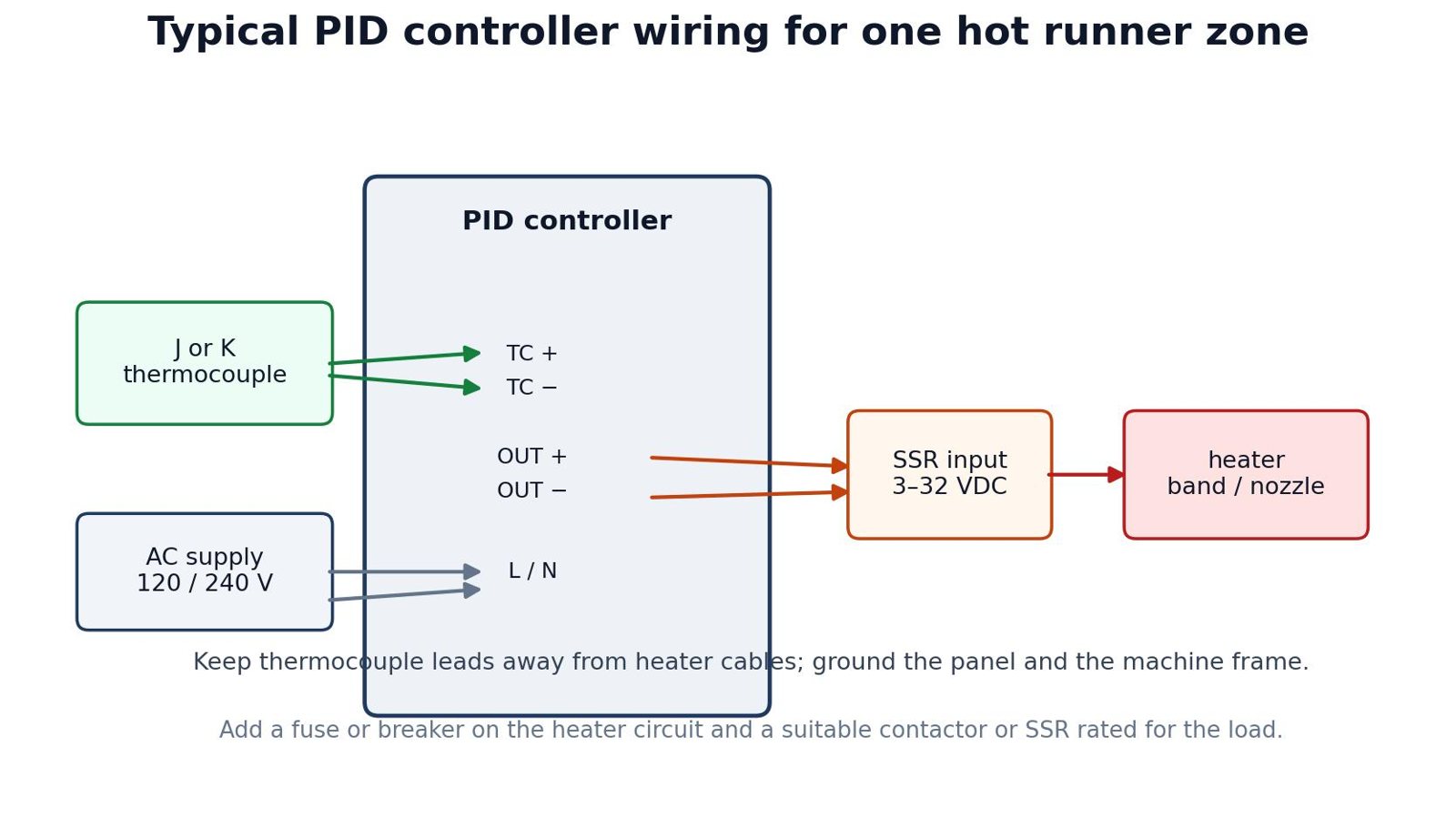
PID controller vs on/off, fuzzy and PLC control
PID isn't the only way to hold heat. On/off is cheaper. Heater on below the threshold, off above it. Fine for a tank or an oven where a few degrees of swing don't matter. On a nozzle, that swing shows up in melt viscosity and part quality.
Fuzzy logic adds rules and can handle a load that changes character. Useful in some processes. Harder to document. Harder for a new maintenance tech to tune without the original supplier on the phone.
PLC and touch screen systems bring recipes, data and one place to watch dozens of zones. Great on a big mold. Too much cost and programming for a four-zone job.
| Control method | Strength | Weakness | Typical use |
|---|---|---|---|
| On/off | Low cost, easy to understand | Overshoot and cycling | Ovens, tanks, non-critical heaters |
| PID | Stable control, well understood | Needs correct sensor and tuning | Hot runner nozzles, manifolds, precision molds |
| Fuzzy logic | Handles non-linear and changing loads | Harder to document and tune | Processes with large load changes |
| PLC / touch screen | Central control, recipes, data | Higher cost and programming effort | Large multi-zone molds and automated cells |
None of this is about which method sounds modern. It's about how much variation the part can take and how much skill is on the floor at 2 a.m. A plain PID controller with a good sensor beats a clever algorithm fed by a bad signal.
Who specifies which controller
The person who signs the PO usually isn't the person who has to fix the zone. That gap causes a lot of bad purchases.
| Role | Main concern | What to ask for |
|---|---|---|
| Mold maker | Fits the mold, starts up quickly | Correct zone count, connector type, compact cabinet |
| Injection molding engineer | Stable temperature and short cycle | PID or PIDD, fast sampling, clear alarms |
| Maintenance technician | Easy replacement and diagnosis | Plug-in modules, labeled terminals, spare cards |
| Purchasing | Total cost and lead time | Spare parts availability, warranty, OEM terms |
| Distributor | Sellable range and local support | Model coverage, documentation, packaging |
A PID controller that's perfect for a mold maker can be a nightmare for maintenance if every card is soldered in. A controller that's perfect for a big plant is overkill for a four-zone mold. Ask who will run it for the next five years.
If two people own different parts of the PID controller specification, put it on one sheet. The mold maker's thread callout and the buyer's input type belong in the same document.
How TOPOWER controllers fit the loop
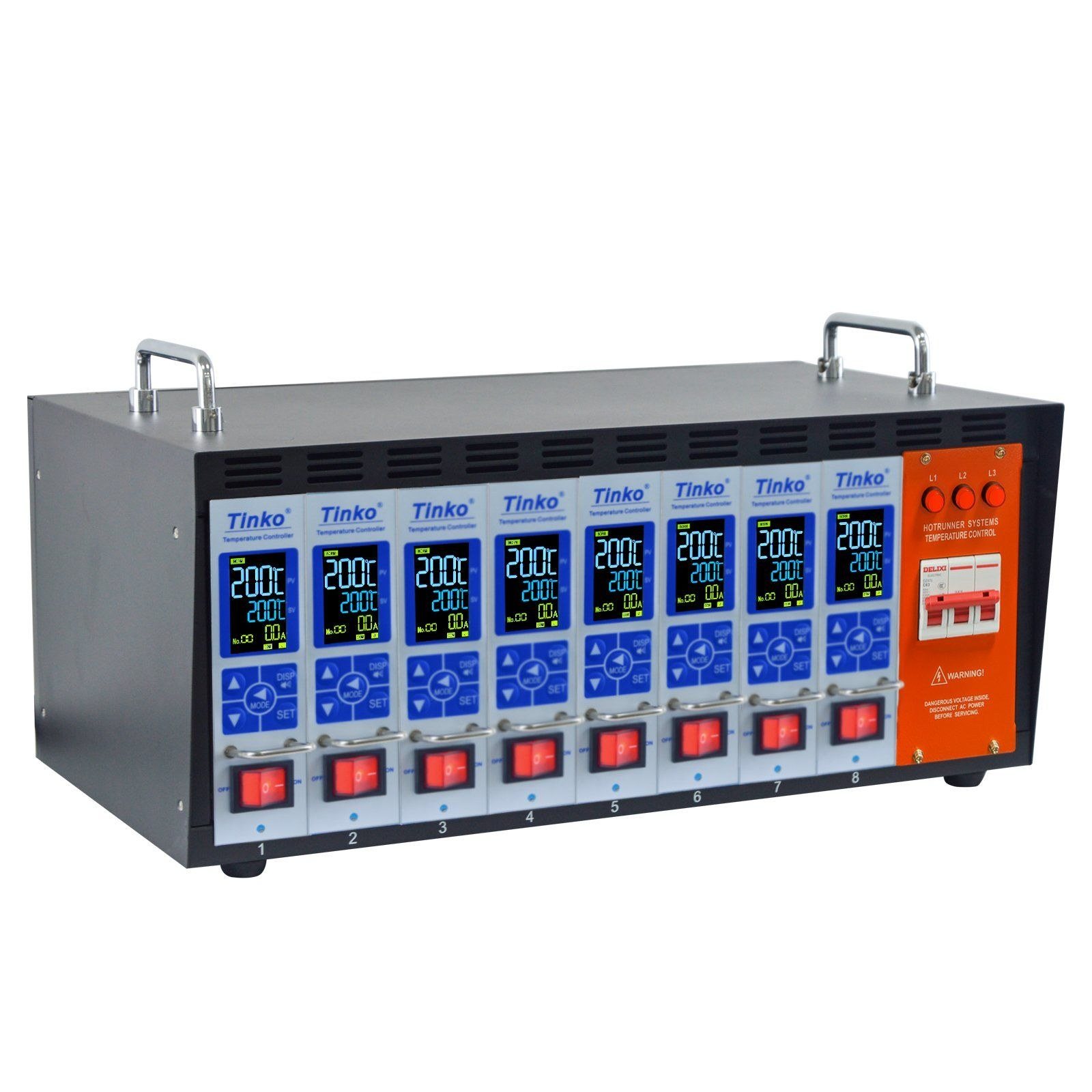
TOPOWER builds hot runner temperature controllers around this same loop. The range runs from one zone to 120, so a mold shop doesn't have to switch suppliers every time a bigger mold shows up.
The TP01 modular hot runner temperature controller uses plug-in cards for 1, 2, 4, 6, 8, 12 and 16-zone systems. Replace one card, not the whole cabinet. That's the point for a small or medium mold.
The HY20 touch screen hot runner controller is built for 12 to 120 zones. Central operation, alarms you can see, remote monitoring if the plant wants it. Better fit when one operator watches a lot of zones.
Both families run PID or PIDD, read J or K thermocouples, sample at 10 Hz and quote ±0.1% control accuracy on the product page. The TP01 16-zone model lists 3,600 W per zone at 240 VAC. CE and RoHS options, a one-year warranty, OEM logo and color are available.
The whole range sits under hot runner temperature controllers. For a specific quote, start with the TP01 16-zone controller page. It shows terminals, thermocouple options and cable connectors.
A troubleshooting order for unstable temperature
Don't touch P, I and D first. Work through the physical loop. The sequence below saves more time than any tuning trick.
Check the setpoint, the sensor type and the actual reading. Then check the heater and the output. Measure resistance. Inspect the terminal. Confirm the relay or SSR is switching. A partly failed heater still draws current and still feels warm. Then check sensor placement. A loose probe reads low on the way up. A probe touching a cold plate reads the plate. Then check wiring for noise and ground loops. Then check panel temperature. Tuning comes last.
Why this order? Because tuning a loop around a bad sensor gives you a controller that's stable on the display and wrong in the melt.
| Symptom | First check | Typical cause |
|---|---|---|
| Temperature reads room value while heater is on | Sensor type and polarity | Wrong thermocouple type, reversed leads, broken sensor |
| Zone overshoots and cycles | Output stage and sensor lag | Oversized heater, loose probe, integral too aggressive |
| Temperature drifts down under load | Heater resistance and supply | Failed heater, undersized output, low supply voltage |
| Reading jumps randomly | Cable routing and shielding | Thermocouple cable run beside heater power, ground loop |
| Alarm appears at startup | Alarm settings and sensor | Open thermocouple, wrong alarm limit, cold-start condition |
A PID controller that's fine on a cold mold can still cycle on a hot mold. Run the check again under production conditions. The loop changes when the mold is full.
Write down what you changed. A PID controller with a log of setpoint, sensor and output readings is easier to diagnose than one with a clean memory.
The market behind the box
PID controllers are old technology. The market still grows. Fortune Business Insights puts the global PID controller market at about USD 1.72 billion in 2025, heading for USD 2.49 billion by 2034 at a 4.2% compound annual growth rate. Definitions vary by report. The direction doesn't.
For a mold shop, the useful part is supply, not the market total. Lead time. Spare card price. Whether the supplier will support an OEM label. A cheap 24-zone cabinet isn't cheap if a card takes eight weeks to arrive.
Compare like with like. A panel-mount PID controller, a modular card and a PLC touch screen solve different problems. The lowest price per zone is rarely the lowest cost per production hour.
The PID controller market also includes process industries, HVAC and laboratory equipment, so much of that volume has nothing to do with injection molding. Don't read a total market number as a mold shop forecast. Use it as a reminder that suppliers have options, and that one who understands hot runner zones is worth more than a catalog with a hundred models.
What changes in the next few years
Three things are moving. Controllers are becoming data sources. Ethernet, Modbus and remote monitoring are no longer optional on big systems, because plants want zone health without walking to the cabinet.
The line between a dedicated controller and a PLC is blurring. Touch screens store recipes and log alarms. Modular PID controller cards keep getting cheaper and easier to replace. Buyers can pick the integration level their maintenance team can actually support.
Heat and energy are getting more attention. Better heat sinking, faster switching and clearer power measurement help plants catch a dying heater before it scraps a run. The PID controller is turning into part of the maintenance system, not just a display.
A fourth change is documentation. More buyers ask for wiring diagrams, terminal maps and a PID controller setting sheet in the box. Small request, big payoff during a midnight breakdown. If the supplier can't provide it, ask why.
None of that changes the basics. Correct sensor. Correct output. Tune under real conditions. Those three still beat a fancier box with a bad installation.
FAQ
What does a PID controller do in a hot runner system?
Reads the zone thermocouple, compares it with setpoint, and adjusts heater power. It repeats that comparison many times a second and uses the error history to brake before overshoot. That's it. The rest is setup.
Is a PID controller the same as a temperature controller?
No. Temperature controller is the box category. PID is one algorithm inside it. Plenty of temperature controllers also offer on/off and fuzzy control, so the label doesn't tell you what's running.
Why does my zone overshoot after a setpoint change?
Heat is still arriving after the sensor hits setpoint. Loose probe, oversized heater, too much integral, or derivative switched off when it shouldn't be. Check the mechanical side before the tuning.
Can I use the same tuning values on another mold?
As a starting point, sure. Then verify. Heater wattage, thermal mass, probe location and controller sampling all change the response. A 4-zone mold isn't a 16-zone mold.
Does a PID controller need derivative control on a hot runner zone?
Not always. D helps when the zone approaches fast and tends to overshoot. On a noisy signal or a tiny zone, a clean PI loop can be steadier than a PID loop fighting noise.
Why does a PID controller show a temperature when the thermocouple is disconnected?
Some models show an open-circuit value or a default instead of an error. Check the sensor-break alarm setting. Test the input with a known signal before you trust the display.
What is the difference between a PID controller and PIDD control?
PIDD adds a second derivative term. Sometimes it improves response on a difficult thermal load. On most hot runner zones the practical difference is small, and the extra term has to be tuned carefully.
How many spare zones should a PID controller have?
One or two for a small mold. More if the shop keeps adding cavities. Spare capacity is cheaper than a new cabinet when the next mold arrives.
Does a faster PID controller always improve control?
No. Fast sampling helps only if the sensor and output can keep up. A fast controller reading a heavy, slow probe will still overshoot. The delay is in the heat path.
When should I replace a PID controller instead of tuning it?
When the input is unstable, the output stage is failing, the keys or display are unreliable, or the model no longer matches the sensor and heater. Tuning can't fix hardware.
Can a PID controller be too precise?
You can chase tenths of a degree and still scrap parts. Melt temperature, residence time and gate balance matter more than a perfect display. Use the PID controller to hold a stable band, not to win a number contest.
Choosing a supplier for the next mold
Price is one line. Ask for zone range, sensor types, output rating per zone, spare card price and lead time. Ask what happens when a thermocouple breaks. Ask whether the alarm is visible without opening the cabinet.
If the mold already runs, send zone count, heater wattage, supply voltage, thermocouple type and the connector on the mold. A supplier who can match those without ten emails is easier to deal with when a mold is down. TOPOWER's contact page takes that information directly. The modular controller range and the controller accessories cover most replacement and expansion jobs.
For the algorithm, the PID controller overview on Wikipedia is a decent start. NI's PID theory guide and Omega's PID controller resources go further. The market figure above comes from Fortune Business Insights. Thermocouple reference tables live at NIST.
Related reading: the temperature controller selection guide, the digital temperature controller guide, and the hot runner controller troubleshooting guide. For a wider project, the hot runner controller guide and the hot runner system overview fill in the rest.
Two components are worth a look before the next cabinet. The K type thermocouple guide covers the sensor side. The solid state relay selection guide covers the output side. The hot runner system articles and the applications page show how the pieces land on real molds.