
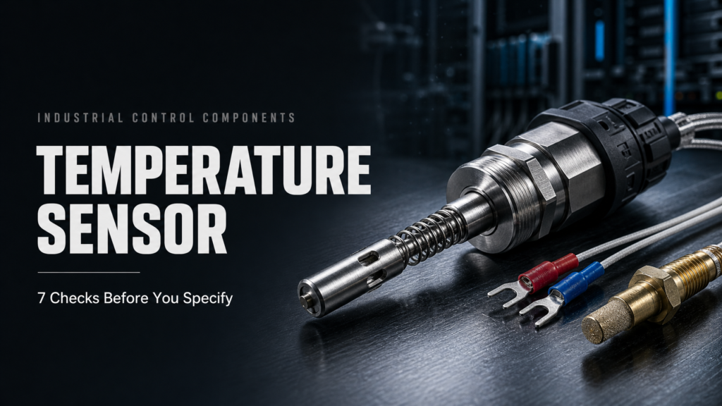
A 24-zone manifold shows up reading 18 °C low on every zone. Same controller. Same heaters. Same setpoints. The sensors were swapped last month, maintenance checked two of them against a handheld meter, and both looked close enough. So an offset went into the controller and the mold went back into production.
Two weeks later the parts start short-shotting near the gate. The temperature sensor wasn't off by 18 degrees. It was reading the wrong place, slowly, and the controller was holding that wrong place steady.
Cheap part. Fits in a pocket. Looks the same as the one it replaces. Except the junction is different, or the tolerance class is looser, or the probe is six millimeters too short, or the cable insulation can't take the heat where it leaves the mold. The zone still runs. It runs wrong.
Here's the short version, then the details.
What a temperature sensor does inside a hot runner mold
The job sounds simple. Turn heat into a signal. The controller reads the signal and does the math.
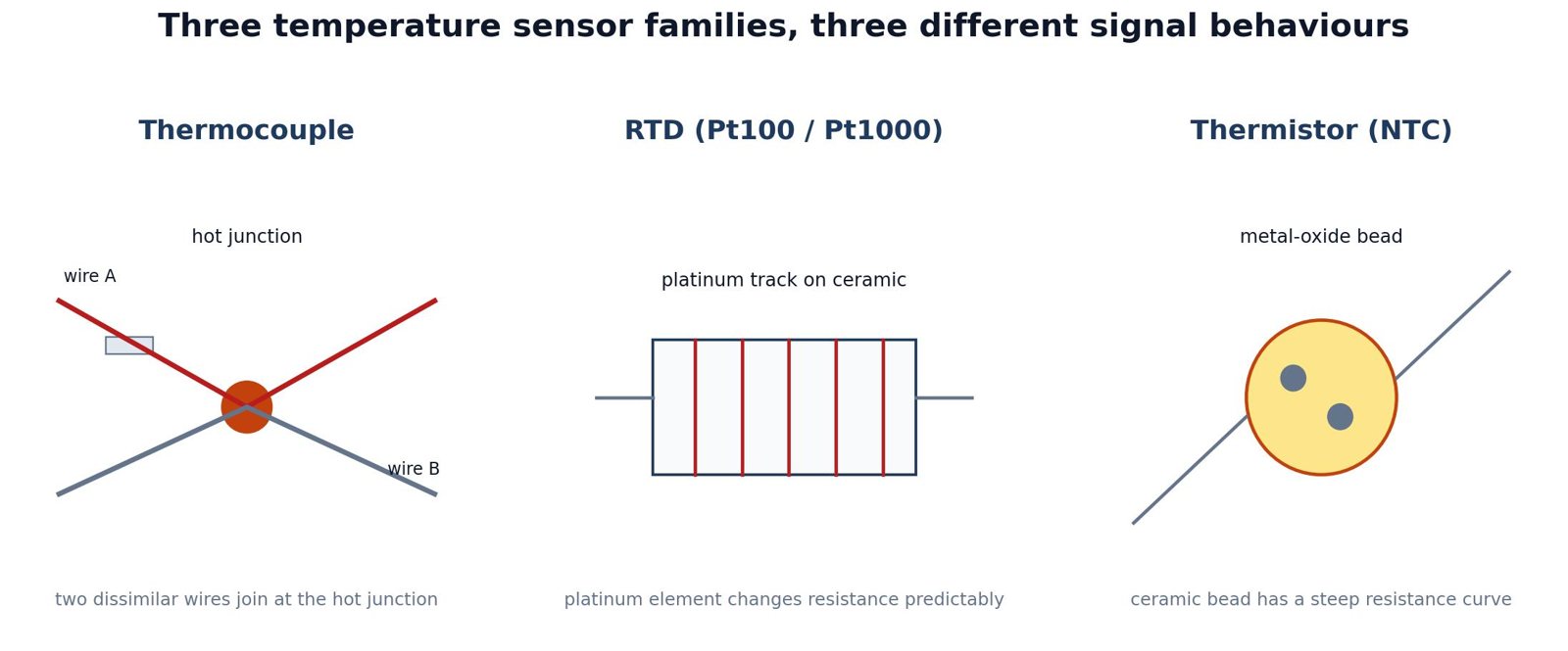
A thermocouple is two wires of different metals welded at the tip. Heat at that junction makes a tiny voltage. Reverse the wires and the reading goes the wrong way. Fit the wrong alloy and it goes the wrong way more slowly, which is worse because nobody notices.
An RTD is a platinum track on a ceramic wafer. Resistance climbs as it warms. Steady. Accurate. Slower than a bare thermocouple. A thermistor is a ceramic bead with a steep resistance curve. Very sensitive, very narrow range. Infrared reads the radiation off a surface and never touches it.
Different physics, different failure habits. A thermocouple loses its junction. An RTD gets wired with the wrong number of leads. A thermistor cracks. Infrared sees a reflection and calls it temperature. Inside a closed mold, that last one is mostly a bad idea.
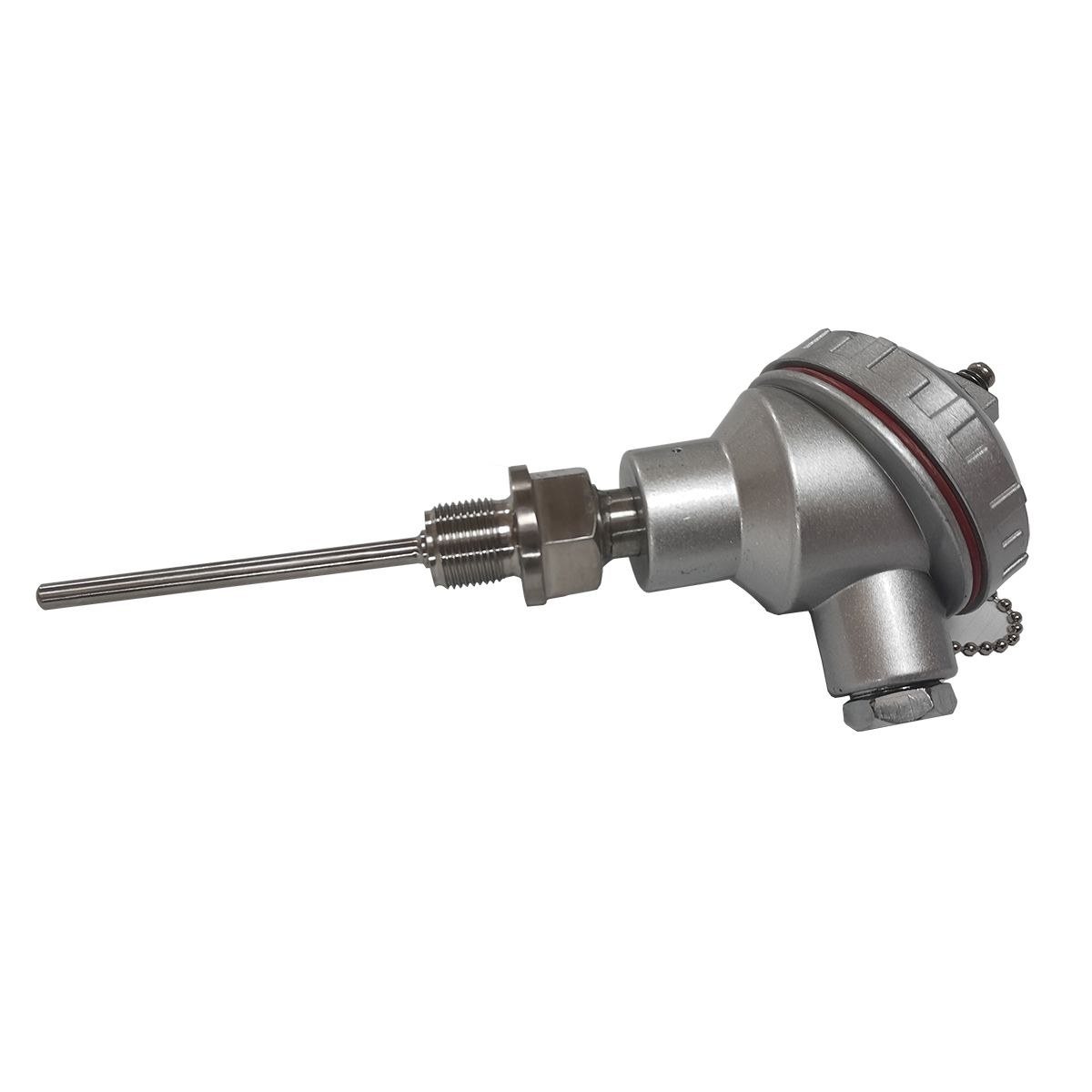
And every temperature sensor has a mechanical job. Stay against the metal that carries the melt. Survive heat cycles and mold changes. Let the cable leave without a pinch. A probe that's electrically perfect but mechanically loose reads low and late. Tuning can't fix that.
Four temperature sensor families and where each one fits
Thermocouples own hot runner work. A J or K junction fits into a nozzle tip or a manifold channel where an RTD would be too fat. They're fast. The trade-off is accuracy. A standard thermocouple is often ±2.2 °C or ±0.75% of reading, and the cold junction and extension wire become part of the measurement whether you like it or not.
An RTD, usually Pt100 or Pt1000, is steadier. A Pt100 sits at 100 Ω at 0 °C and moves about 0.385 Ω per °C. Great in process piping and lab gear where repeatability beats speed. In a hot runner mold it works if there's room for the probe and the controller input matches. The extra mass usually makes it slower than a fine-wire thermocouple.
Thermistors are tiny and sensitive. An NTC bead resolves a fraction of a degree over a narrow band, which is why electronics love them. Steep curve, limited range, not the first choice for a 300 °C nozzle.
Infrared reads without contact. Moving webs, rotating parts, surfaces you can't touch. Inside a mold, the target is hidden or reflective or both. Not a good fit for closed-loop nozzle control.
Placement matters more than the catalog. A nozzle probe should sit close to the melt channel, not in the heater pocket. A manifold probe belongs in the steel near the flow path, not at the edge where it reads the plate. A valve gate probe should be near the gate body, where the tip temperature actually matters. Two inches in the wrong direction can add several degrees of error and a lot of lag. Before changing sensor type, look at where the old one sat and whether the hole is still round and clean.
| Sensor family | Typical range | Strength | Weakness in a hot runner |
|---|---|---|---|
| J thermocouple | −40 to 750 °C | Fast, small, low cost | Lower accuracy, iron leg can corrode |
| K thermocouple | −200 to 1,260 °C | Wide range, common worldwide | Drift with age, needs correct extension wire |
| Pt100 / Pt1000 RTD | −200 to 600 °C | Stable, accurate, repeatable | Larger, slower, needs matching input |
| NTC thermistor | −50 to 300 °C | High sensitivity, small | Non-linear, limited range, fragile |
| Infrared | Depends on optics | No contact, fast surface reading | Emissivity and line-of-sight problems |
The specifications that decide whether the reading is useful
The catalog says ±0.5 °C. The mold doesn't care about the catalog. What matters is the element tolerance plus cold-junction compensation plus extension wire plus the controller input. Put a Class 1 thermocouple on a controller with sloppy cold-junction compensation and you can beat it with a standard sensor on a good input.
Range is the first filter. A temperature sensor rated to 400 °C has no business on a manifold running 420 °C, even if it reads fine on the bench. Check the sheath, the insulation and the cable exit. The hottest point is usually where the cable leaves the mold, not the tip.
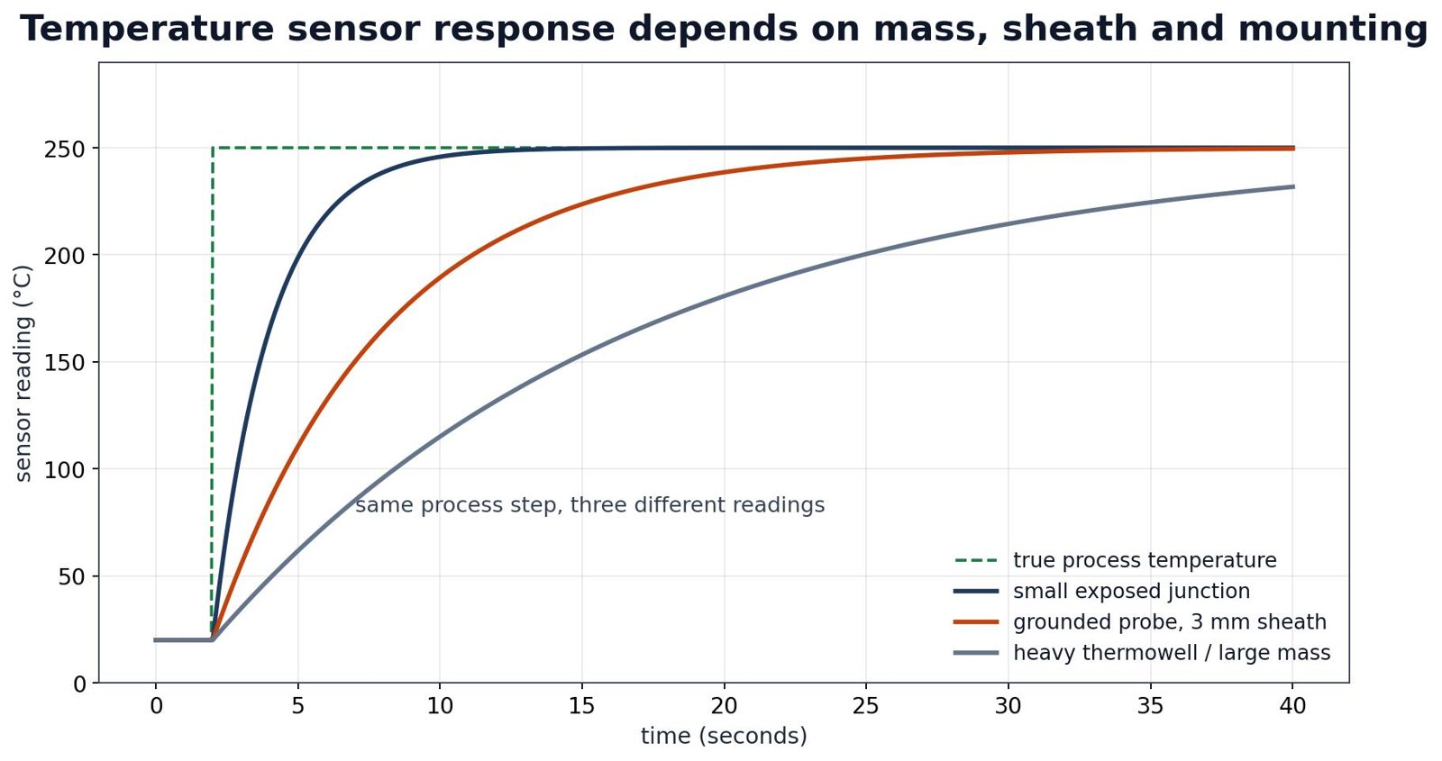
Response is the second filter. A thin exposed junction moves in a fraction of a second. A heavy probe in a thermowell takes tens of seconds. The controller samples at 10 Hz and expects the temperature sensor to keep up. A slow sensor makes the loop look calm while the melt is still moving.
Then drift. A temperature sensor that reads 2 °C low every time can be compensated. One that wanders can't. For a critical zone, write down the type, class and install date. The next replacement needs something to compare against.
Finally the package. Thread. Probe diameter. Bend radius. Connector. Cable length. A temperature sensor that fits the hole but can't be routed without a sharp bend will fail at the cable, not at the junction.
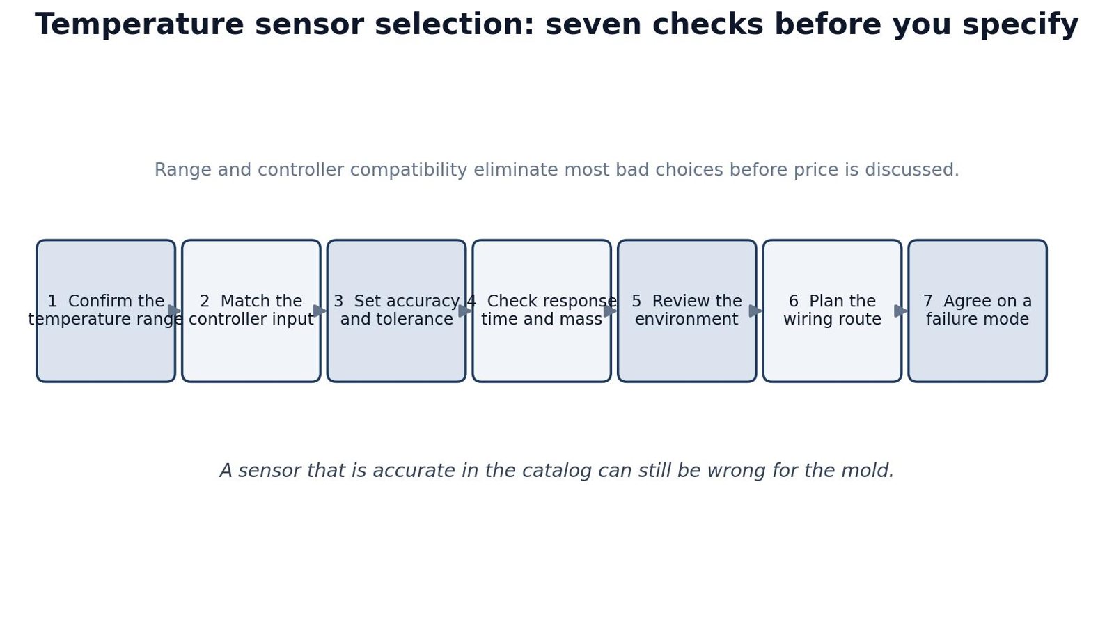
Seven checks before you specify a temperature sensor
Don't match the plug color. That's not a spec. Work through these instead.
One. Range. Process temperature, startup, purge, engineering resins. Add headroom. If the cable exits near a heater, check the insulation on the cable, not just the probe.
Two. Controller input. J or K. Pt100 or Pt1000. The temperature sensor only works if the controller reads that type. A mismatch gives you a believable wrong number.
Three. Accuracy and class. Standard tolerance for a general nozzle. Tighter class for a manifold zone that controls color or flow. Decide before you compare price, because price will pull you the wrong way.
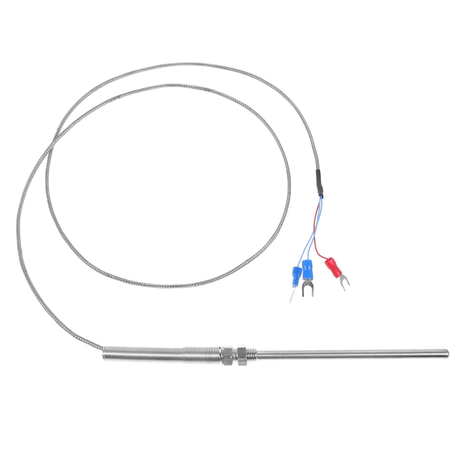
Four. Response and mass. Small exposed junction when speed matters. Grounded junction in a stainless sheath as a compromise. Heavy thermowell only when the process needs the protection.
Five. Environment. Abrasion, vibration, moisture, cleaning chemicals, repeated disassembly. The temperature sensor has to survive the maintenance routine, not just the molding cycle.
Six. Wiring route. Keep the cable away from heater power. Use the right extension wire. Decide where the shield is grounded. A good element on a bad route is still a noisy signal.
Seven. Failure mode. What should the controller do when the temperature sensor opens, shorts or drifts? A sensor-break alarm that stops the zone is safer than a controller that keeps heating on a default value.
Response time, mass and thermal lag
Thermal lag is the gap between a change in the process and a change in the reading. It comes from sensor mass, sheath thickness, contact pressure and distance from the heater. A temperature sensor can't report heat that hasn't reached it.
That's why two zones with the same controller and the same heater can act completely differently. A spring-loaded nozzle probe touches metal and responds fast. A sensor sitting loose in a deep well responds slowly and reads low while the zone climbs. The controller sees the late signal, adds more power, and overshoots.
Fix it mechanically. Correct probe length. Spring or clamp pressure. Thermal compound only where the manufacturer allows it. Don't fill a thermowell with random grease. Some compounds break down at molding temperature and leave a carbon layer that insulates the temperature sensor.
Test the response. Heat the zone in manual, watch the reading, compare it with a known reference, and time how long it takes to settle. If one zone is much slower than its neighbors, inspect the mounting before you touch PID settings.
One practical check: run the zone at 220, 260 and 300 °C. Let each settle. Compare the reading with a calibrated reference at the same point. If the error changes with temperature, the thermocouple or input is suspect. If the error stays constant, an offset may be acceptable until the next maintenance window.
Wiring a temperature sensor without adding error
Thermocouple rules are simple and easy to break. Use extension wire of the same type. Respect polarity. Ordinary copper cable creates a new junction at the terminal and shifts the reading. Reversed leads read fine at room temperature and get worse as the mold heats.
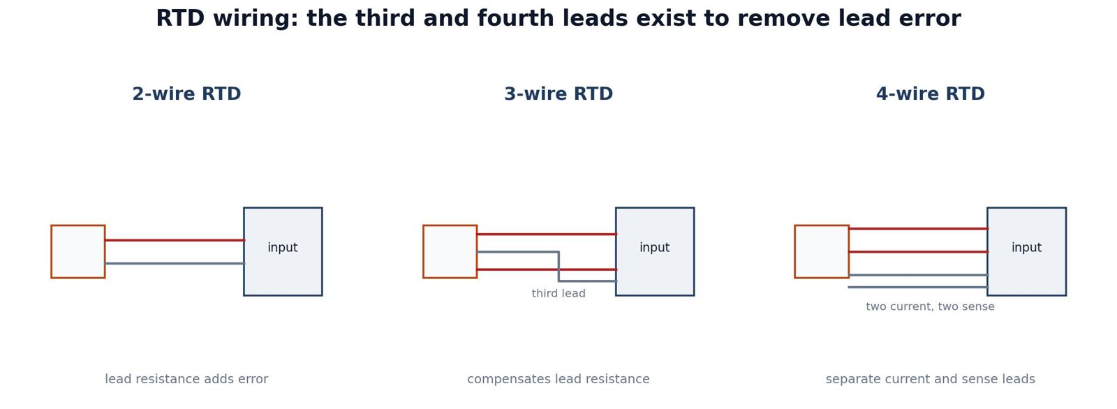
RTD rules are different. Match the lead count to the controller. Two-wire puts lead resistance in the measurement. Three-wire compensates for it. Four-wire separates current and sense leads. Connect a three-wire temperature sensor to a two-wire input and you've built a fixed error that changes with cable length and temperature.
Shield both types. Ground the shield at one end, usually the cabinet, and leave the other end open. Ground both ends and you've made a loop that picks up current from nearby equipment. Route sensor cable away from heater cable. If they cross, cross at 90°.
Label both ends and record the type. A temperature sensor replaced with the wrong type during a maintenance shift can cost a day of troubleshooting. A small tag is cheap.
Calibration doesn't have to be a lab project. A dry-block calibrator and a known reference are enough for most shops. Check the probe at the temperature the zone actually runs, not just at room temperature. Record the result. Repeat after any replacement or mold change. If the reading moves more than the process can tolerate, replace the probe and check the input.
Temperature sensor vs thermocouple vs RTD vs thermistor
The names overlap. A thermocouple is a temperature sensor. So is an RTD. So is a thermistor. The useful question isn't which name sounds better. It's which sensing method fits the zone.
Nozzles and manifolds usually want a thermocouple. Size and speed win. Process measurement where accuracy and stability matter may want an RTD. A low-temperature electronic assembly may want a thermistor. A moving surface may need infrared.
| Decision factor | Thermocouple | RTD | Thermistor |
|---|---|---|---|
| Temperature range | Wide | Medium to wide | Narrow |
| Accuracy | Moderate | High | High in a narrow band |
| Response speed | Fast | Moderate | Fast |
| Size | Very small | Larger | Very small |
| Cost | Low | Medium | Low |
| Best fit | Nozzles, manifolds, general mold zones | Stable process measurement | Electronics and low-temperature control |
The table is a starting point. A temperature sensor that fits the mechanics and the controller input beats a theoretically better sensor that's loose, miswired or out of range.
Who specifies which temperature sensor
The sensor decision usually gets split across roles. Mold maker picks the hole and thread. Process engineer picks the temperature and tolerance. Maintenance picks the replacement. Purchasing picks the supplier. If nobody owns the whole spec, the zone ends up with a sensor that fits but doesn't measure.
| Role | Main concern | What to confirm |
|---|---|---|
| Mold designer | Space and installation | Probe diameter, thread, bend radius, cable exit |
| Process engineer | Accuracy and response | Type, tolerance class, junction style, placement |
| Maintenance | Replacement and diagnosis | Labeling, connector, spare part number |
| Purchasing | Cost and lead time | Repeatable specification, approved alternatives |
| Quality | Traceability | Calibration record, batch, installation date |
Write one sheet. Type, class, length, thread, connector, controller input. It prevents most replacement mistakes and makes quotes comparable. A photo of the old sensor next to a ruler saves a lot of back-and-forth.
Pairing a temperature sensor with a TOPOWER controller
The controller has to match the sensor. TOPOWER hot runner temperature controllers read J and K thermocouples, which covers most nozzle and manifold sensors in use. Sampling runs at 10 Hz, and control is PID or PIDD. A fast, well-mounted temperature sensor can actually show up in the result.
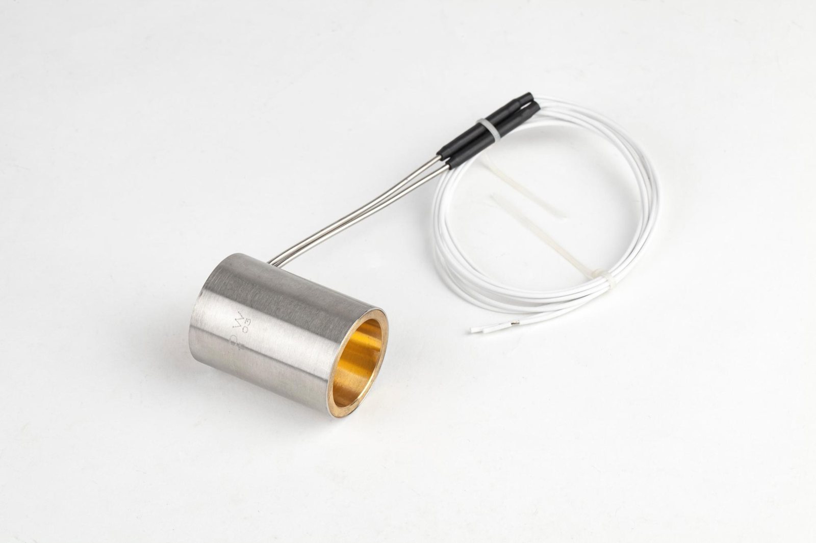
The TP01 modular hot runner temperature controller fits small and medium molds, with 1, 2, 4, 6, 8, 12 and 16-zone cards. Each card has its own input and output, so one bad temperature sensor doesn't take down the cabinet. The HY20 touch screen hot runner controller covers 12 to 120 zones for larger molds that want one place to watch everything.
Both families sit under hot runner temperature controllers. The TP01 12-zone controller page lists the thermocouple input, output rating and connector options for a mid-size mold. Cables and connectors are under hot runner controller accessories. Touch screen models are grouped under touch screen hot runner controllers.
TOPOWER doesn't ask buyers to guess. Send the thermocouple type, zone count, heater wattage per zone, supply voltage and mold connector. That's enough to match a controller and cable set before the mold arrives.
Troubleshooting a temperature sensor that reads wrong
Separate the sensor from the controller before you change settings. The sensor touches the process. It's also the part most likely to get damaged during a mold change.
Reads room temperature with the heater on? Check type, polarity and input configuration. Reading jumps? Check cable route, shield and terminal screws. Reads stable but low? Check probe contact and thermowell fit. Drifts over days? Compare with a reference and look for moisture, corrosion or a failing extension wire.
Don't hide a sensor problem with a controller offset until you know the cause. An offset can match a reference at one temperature and be wrong at another. Fix the temperature sensor, the wiring or the placement first.
| Symptom | Likely sensor cause | Check |
|---|---|---|
| Reads room temperature with heater on | Open junction, wrong type, reversed leads | Sensor type, polarity, continuity |
| Reading jumps or spikes | Noise, loose terminal, damaged cable | Shield grounding, cable route, terminal torque |
| Reads low during heating | Poor contact, loose probe, wrong insertion depth | Spring force, probe length, thermal contact |
| Slow response | Heavy sheath, thermowell, air gap | Sensor mass and mounting method |
| Drifts over time | Moisture, corrosion, aged thermocouple | Insulation resistance, junction condition |
A spare temperature sensor with the same spec is the fastest diagnostic tool. Swap it. Watch the reading. If the problem follows the sensor, you've found it. If it stays with the zone, look at the wiring or the input.
The market behind the sensor
Temperature sensors show up in cars, buildings, appliances and factories, so the market is broad. MarketsandMarkets puts the global market at USD 7.43 billion in 2025, growing to USD 8.94 billion by 2030 at a 3.8% compound annual growth rate. Industrial measurement is one slice. It's the slice that matters here.
For a buyer, the practical result is choice. Many suppliers, many tolerance classes, many connector styles. That makes the spec more important, not less. A cheap temperature sensor that doesn't match the controller input isn't a saving. It's a future downtime event.
Supply matters too. A sensor stocked locally in the right length and thread beats a slightly cheaper one that arrives in six weeks. Get the part number, class and cable length in writing. Keep a spare for critical zones. Ask for a certificate of conformity with the batch; it's a small piece of paper that saves an argument later.
What is changing in temperature sensing
Digital temperature sensors and smart transmitters are moving into industrial equipment. A digital sensor can carry calibration data and report a fault before the reading becomes useless. Nice when maintenance is planned rather than reactive.
Thin-film RTDs and smaller thermocouple packages keep improving. It's easier to fit an accurate temperature sensor into a tight nozzle or manifold. The limiting factor is still the installation and the cable route, not the element.
Remote monitoring is the third change. When a controller reports zone temperature and sensor health over a network, a drifting temperature sensor gets caught before it scraps a batch. The sensor is passive. The data isn't.
None of this removes the basics. Match the sensor to the controller. Mount it against the right metal. Wire it without noise. Replace it with the same spec. Those four habits solve more problems than any new sensing technology. The fifth habit is boring: write down what's installed. Future maintenance will thank you.
FAQ
What is the best temperature sensor for a hot runner mold?
For most nozzles and manifolds, a J or K thermocouple with a spring-loaded or grounded junction. Small, fast, compatible with common controllers. An RTD can be better where accuracy matters more than speed, if the input and the space allow it.
How do I know which temperature sensor type I have?
Check the marking on the plug, cable or body, then compare it with the mold documentation. J often has a black plug, K a green plug. Color alone isn't proof. Measure the signal or check the controller configuration.
Can I replace a J thermocouple with a K thermocouple?
Only if the controller is configured for K and the range suits the process. The voltage curves differ, so a J sensor on a K input reads wrong. Replace with the same type unless you're deliberately changing the spec.
Why does my temperature sensor read low?
Loose probe. Too short for the hole. Air gap or degraded compound between probe and metal. A reversed thermocouple or wrong input type can do it too. Check the mechanical contact before the controller.
How often should a temperature sensor be replaced?
When the reading gets unstable, when it fails a comparison check, or when the cable or connector is damaged. No fixed interval fits every mold. Keep a spare and record the install date.
Does a temperature sensor need calibration?
For critical zones, yes. Compare the sensor and input with a reference at one or more temperatures. For general molding, a same-spec replacement plus a periodic comparison with a known zone is often enough.
What is the difference between a temperature sensor and a thermocouple?
A thermocouple is one type of temperature sensor. The category also includes RTDs, thermistors and infrared. In a mold shop, "temperature sensor" usually means the thermocouple that plugs into the controller.
Can a temperature sensor be too fast?
A fast sensor can reveal noise a slow one hides. That's fine if the wiring is clean and the loop is tuned for it. Speed is usually an advantage, as long as the sensor is tough enough for the mold.
Why does the reading change when I touch the cable?
Movement changes a poor connection, a damaged conductor or a ground loop. It can also shift the probe contact. A reading that responds to touch isn't trustworthy. Inspect the cable, connector and mounting.
Should I use a shielded temperature sensor cable?
Yes, when heater cables run nearby. Ground the shield at one end and keep sensor cable separate from power wiring. Shielding helps. Routing and terminals matter just as much.
Can I use a temperature sensor from another machine?
Only if type, class, length and connector match, and the controller input is the same. A sensor that works on one mold can read wrong on another because the hole depth or metal contact is different. Check the spec, not just the plug.
Why do two zones with the same sensor read differently?
Placement, contact pressure and cable routing. One probe may sit deeper, one hole may be tighter, one cable may run beside a heater. Swap the sensors between zones. If the difference moves with the sensor, it's the sensor. If it stays, it's the installation.
Specifying a temperature sensor for the next mold
Send the full spec: type, class, probe diameter and length, thread, connector, cable length and controller input. Add the zone temperature and mounting location. A supplier who can match those without ten emails is easier to deal with when a mold is down.
TOPOWER's contact page takes that information for controller and cable matching. The applications page shows typical hot runner arrangements, and the hot runner system guide explains where sensors, heaters and controllers sit in the mold. The K type thermocouple guide covers the most common hot runner sensor in more detail.
If the zone is already running, the hot runner controller troubleshooting guide follows the same physical-first order. The digital temperature controller guide explains input configuration. The hot runner controller guide covers the wider cabinet, and the solid state relay selection guide covers the output side.
Background reading: the thermocouple overview on Wikipedia, the resistance thermometer article, and the NIST thermocouple database for standard tables. Texas Instruments keeps a useful temperature sensor overview. The market figure comes from MarketsandMarkets.
For a new cabinet, start with the modular controller range and the technical article archive for related selection and maintenance topics. If the zone matters, keep the spec sheet with the mold. It's the fastest way to replace a probe without guessing.