
What Is a Hot Runner System?
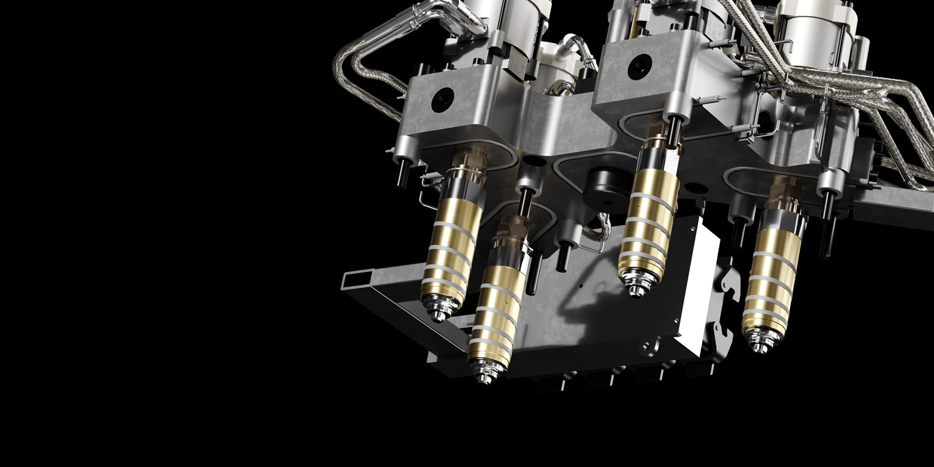
A hot runner system is a heated manifold assembly used in injection molding to keep molten plastic flowing through the mold rather than solidifying between shots. Instead of ejecting the sprue and runner as waste with each cycle, the hot runner maintains the plastic at processing temperature inside the manifold, delivering it directly to each cavity gate. The result — no cold runner waste, faster cycle times, and consistent part quality across multi-cavity molds.
Key components include a heated manifold block, nozzle(s) that deliver melt to the gate, thermocouples for temperature feedback, and a temperature controller that maintains each zone at its setpoint. Modern hot runner systems use PID-controlled heaters with closed-loop feedback, holding temperatures within ±1°C across all zones.
For molders running high-volume production, the hot runner system eliminates regrind costs, reduces labor for runner removal, and improves part consistency. The upfront investment is higher than cold runner tooling, but the per-part cost advantage grows with production volume. Break-even typically occurs within 6-18 months for medium-to-high volume jobs.
How a Hot Runner System Works
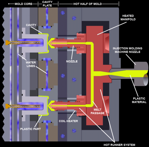
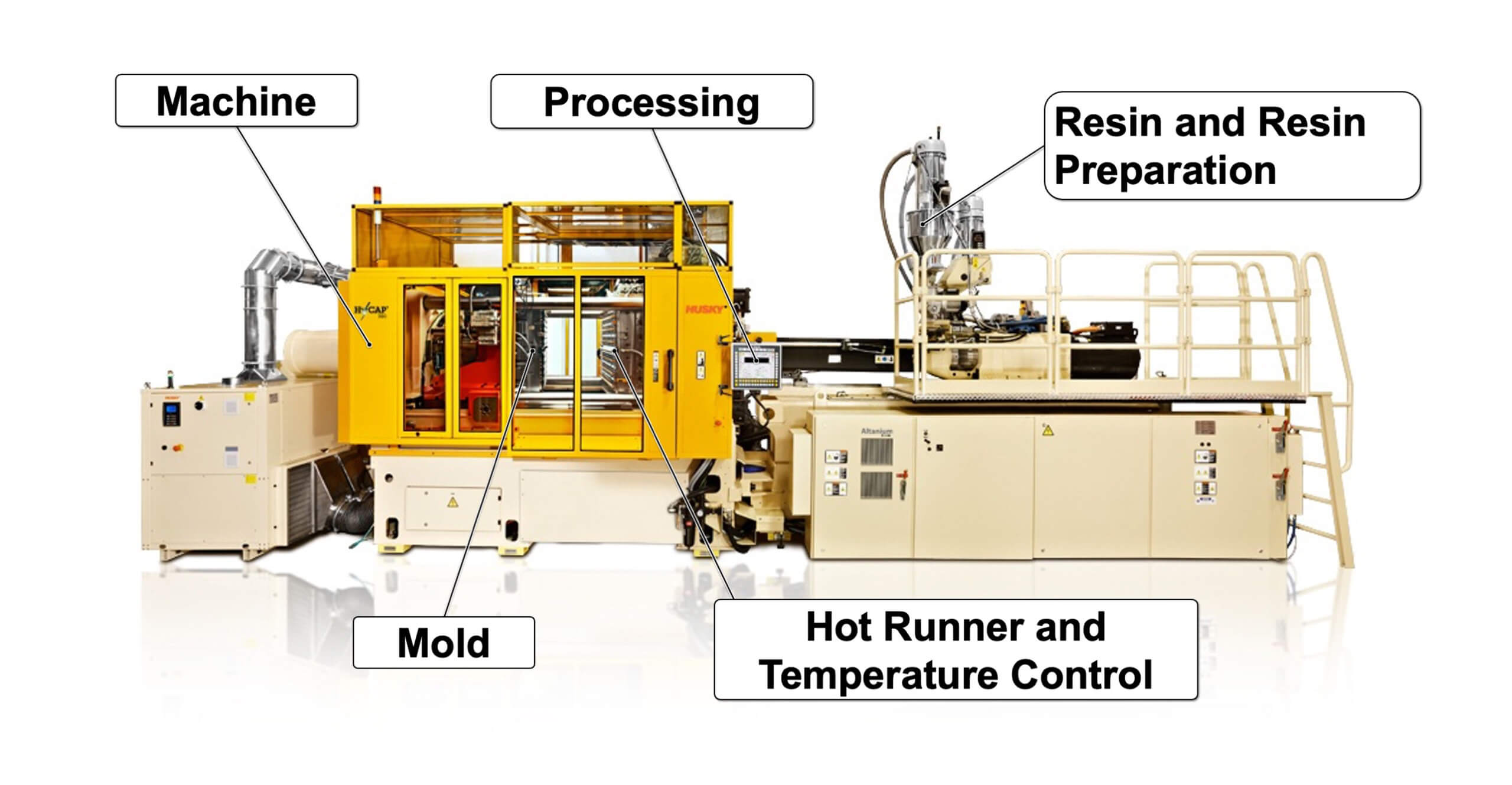
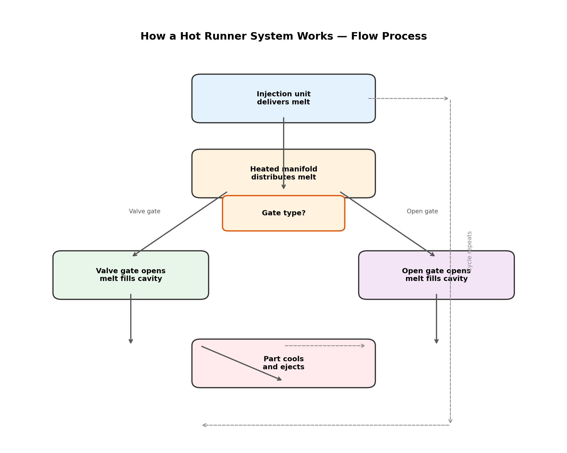
Understanding the flow path helps clarify why hot runner systems deliver such consistent results. Molten plastic enters the manifold from the machine nozzle at the sprue bushing. Inside the manifold, heated channels distribute the melt to each nozzle. Each nozzle contains a heater and thermocouple, independently controlled by the hot runner temperature control system.
The controller reads temperature from each thermocouple and adjusts power to the corresponding heater using PID algorithms. When the mold opens, the nozzle tip at the gate retracts slightly or uses a valve pin to shut off flow. On the next shot, the pin opens and melt flows again instantly — no delay for material to re-melt. This instant response is what makes hot runners faster than cold runners — there is no sprue to cool and eject before the next cycle can start.
A critical detail: the manifold and nozzles are thermally isolated from the mold base, which is cooled. This temperature differential — the manifold at 200-350°C versus the mold at 20-120°C — is what makes the system work. Without proper isolation, heat bleeds into the mold and disrupts part cooling.
Thermal expansion is another factor engineers must account for. A 400mm steel manifold heats from room temperature to 280°C — it expands roughly 1.3mm. The mounting system must allow this movement without stressing the nozzle-to-gate alignment. Most hot runner systems use sliding mounts or flexure-based designs that absorb expansion while maintaining seal integrity. Controllers with soft-start algorithms prevent thermal shock during heat-up by ramping power gradually, giving the steel time to expand evenly.
Multiple temperature control zones are required because different areas of the system lose heat at different rates. Edge nozzles lose more heat than center nozzles. The controller compensates with independent PID loops per zone, typically maintaining ±1°C across the entire system in steady-state operation.
Types of Hot Runner Systems
Two main categories dominate — valve gate and open gate. The choice depends on part design, material, and aesthetic requirements. The mold temperature control strategy also influences system selection.
Valve Gate Hot Runner Systems
A valve gate uses a mechanical pin that opens and closes the gate for each shot. The pin is actuated pneumatically, hydraulically, or electronically. When closed, the pin pushes through the gate opening, shearing off the material and leaving a clean witness mark.
Advantages: clean gate vestige, positive shut-off for materials with low melt strength, ability to sequence gate opening for weld line control. Valve gates are the standard for automotive, medical, and cosmetic parts where gate appearance matters. The main drawback is higher cost and more moving parts that require maintenance.
Open Gate (Thermal Gate) Systems
An open gate relies on the thermal properties of the material to seal the gate between shots. The nozzle tip is heated during injection and allowed to cool slightly after — the material at the tip solidifies, sealing the gate. On the next shot, pressure and heat reopen it.
Simpler and less expensive than valve gates. Works well for polyethylene, polypropylene, and other materials with wide processing windows. Gate appearance is less clean than valve gates, making them more suitable for hidden or non-cosmetic surfaces. Open gate systems require more careful temperature tuning to prevent drooling or freeze-off.
Hot Runner Manifold Types
Manifolds are classified by flow channel design:
Standard manifold — straight flow channels with simple geometry for basic multi-cavity layouts. Cost-effective, easy to maintain.
Stacked manifold — two or more manifold plates stacked vertically, each feeding a separate mold parting line. Doubles output without increasing clamp tonnage proportionally. Stacked molds require specialized hot runner systems with longer nozzles to reach both parting lines.
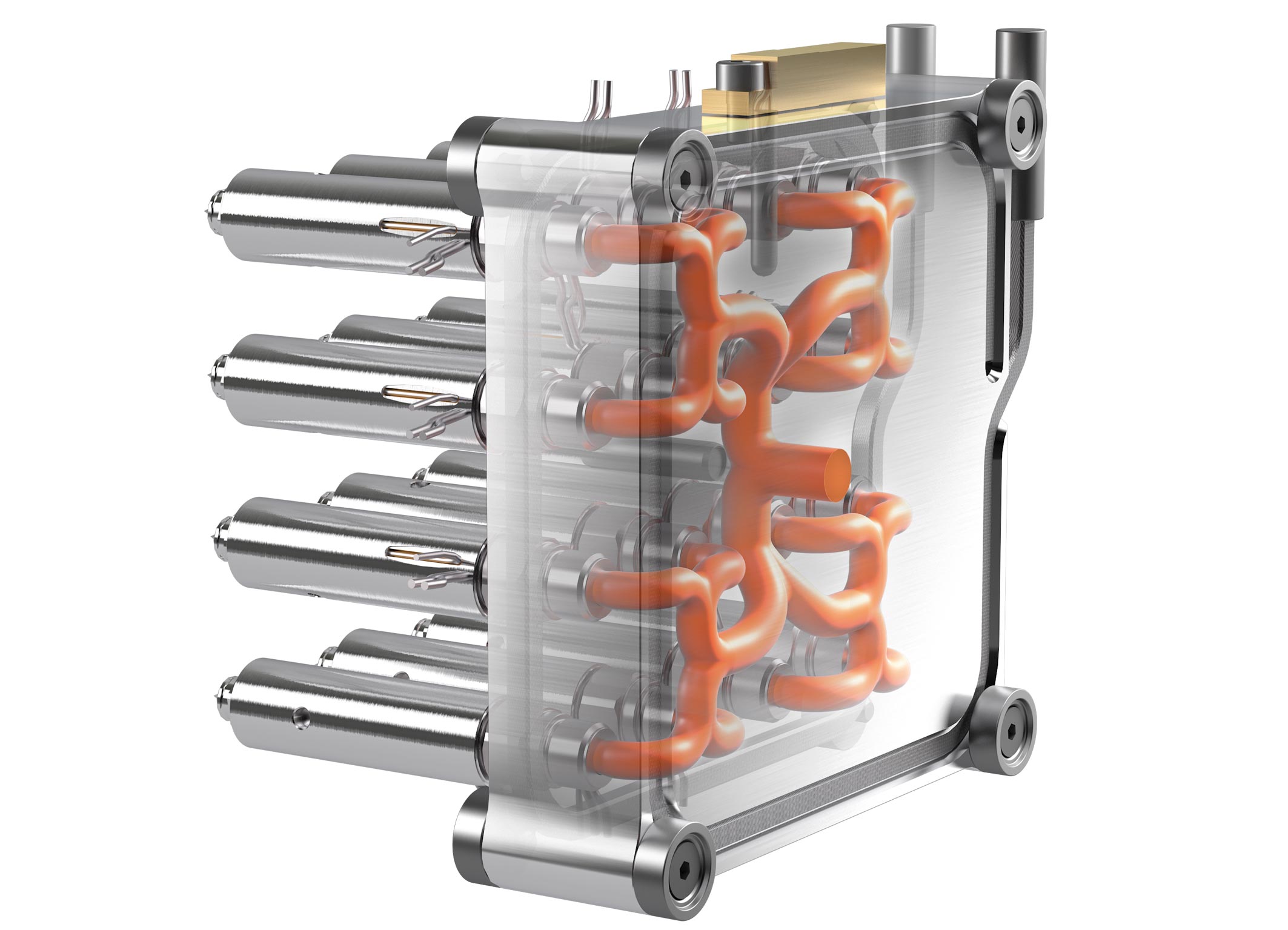
Multi-level manifold — complex 3D channel routing for challenging cavity layouts. Used when cavity spacing is irregular or when gates must be placed at different distances from the sprue. These systems require advanced machining and are more expensive to service.
Key Components of a Hot Runner System
Every hot runner system consists of several precision components that must work together reliably at high temperature for millions of cycles.
Manifold block — machined from hardened tool steel (typically H13 or stainless). Contains the flow channels that distribute melt from the sprue bushing to each nozzle. The manifold expands thermally during heat-up, so mounting must account for movement.
Nozzles — each cavity has a nozzle that delivers melt through the mold plate to the gate. Nozzles are available in different lengths, tip designs, and heater configurations. The nozzle length must match the mold plate thickness exactly. Nozzle tip design is critical for gate quality and freeze-off prevention.
Heaters — band heaters around nozzles and tubular heaters inside manifold channels. Heater wattage is calculated based on the mass of steel to be heated and the target operating temperature. Typical watt densities range from 15 to 40 W/cm².
Thermocouples — Type J or Type K thermocouples embedded in the nozzle body and manifold provide temperature feedback to the controller. Thermocouple placement is critical — too far from the melt channel and the reading lags; too close and it may be damaged by flow pressure.
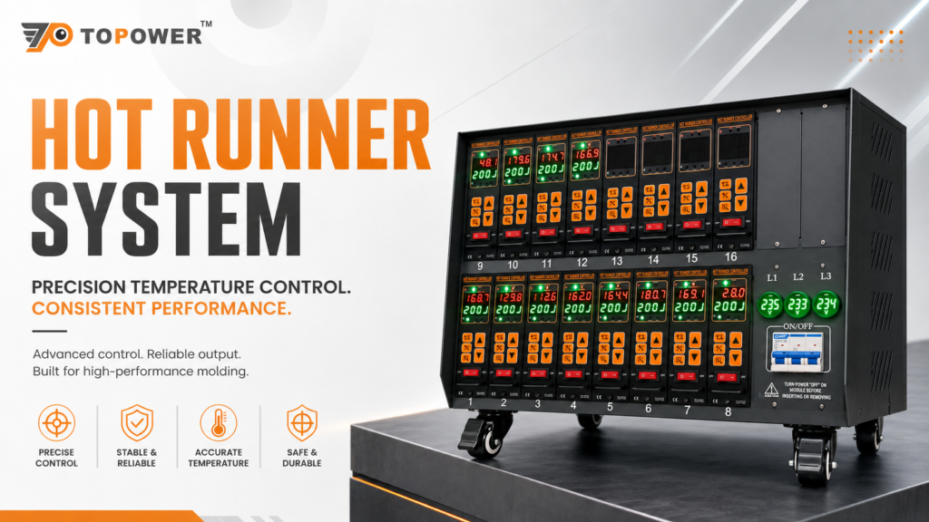
Temperature controller — the brain of the system. The hot runner controller runs PID loops for each zone, logs temperature data, triggers alarms on deviation, and communicates with the injection molding machine. Systems range from 1-zone modular units to 60+ zone touch-screen controllers.
Drop extensions / spacer plates — used when the nozzle must pass through a thick mold plate or when the gate-to-plate-distance exceeds standard nozzle length.
Hot Runner System vs. Cold Runner System
A direct comparison helps clarify when each approach makes sense.
| Factor | Hot Runner System | Cold Runner System |
|---|---|---|
| Material waste | None — no sprue or runner | 15-50% of shot weight as waste/regrind |
| Cycle time | Faster — no runner cooling time | Slower — must cool and eject runner |
| Tooling cost | Higher initial investment | Lower initial cost |
| Maintenance | More complex — heater/controller maintenance | Simpler — fewer components |
| Gate quality | Clean, consistent gate vestige | Gate mark varies, may need post-processing |
| Material compatibility | Most thermoplastics (excluding PVC, some nylons) | All thermoplastics |
| Color change | Slower — manifold volume must be purged | Faster — small cold runner volume |
| Best for | High volume, multi-cavity, precision parts | Low volume, prototyping, frequent material changes |
Applications of Hot Runner Systems
Hot runner technology is dominant in high-volume injection molding across several industries.
Automotive — interior trim panels, dashboard components, connector housings, under-hood parts. Automotive molders run multi-cavity hot runner tools with 8, 16, even 64 cavities, running 24/7 for millions of parts per year. Valve gate systems are preferred for visible interior surfaces. The ability to sequence gate opening also helps control weld line positions on structural parts.
Medical — syringe barrels, IV components, surgical instrument handles, diagnostic device parts. Medical molding demands zero contamination, so hot runners eliminate the risk of regrind reintroduction and reduce particle generation from runner grinding. FDA and ISO 13485 compliance is easier to maintain with closed-loop material handling.
Packaging — bottle caps, food containers, thin-wall tubs. Packaging molds often run 48 to 144 cavities with hot runner systems feeding each cavity through a naturally balanced manifold. Cycle times under 5 seconds demand responsive temperature control. The elimination of regrind also prevents contamination in food-contact applications. Proper heater band selection is essential for consistent nozzle heating.
Consumer goods — cosmetic packaging, pen barrels, toothbrush handles, small appliance housings. Hot runners allow multi-material molding and in-mold assembly for complex consumer products.
Electronics — connectors, LED housings, switch bodies, battery components. Precision hot runner systems with small shot weights rely on stable temperature control to fill micro-features consistently.
How to Choose the Right Hot Runner System
Selecting a hot runner system involves evaluating several factors in sequence.
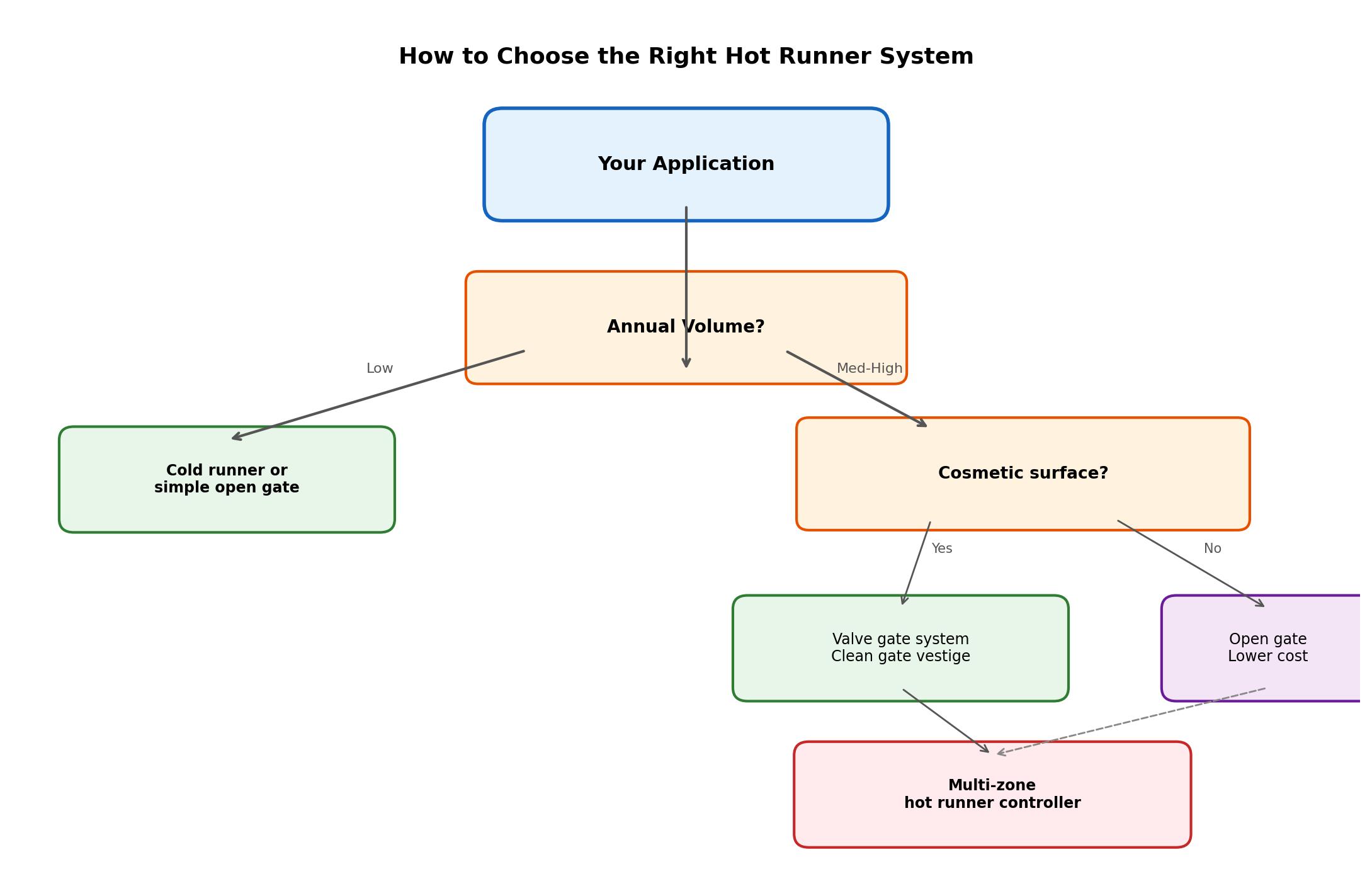
Step 1 — Define your part requirements. Material type, gate location restrictions, aesthetic requirements (visible gate or hidden), and annual volume. Parts with cosmetic surfaces usually need valve gates. High volumes justify the higher upfront cost.
Step 2 — Determine cavity count and layout. More cavities spread tooling cost but increase system complexity. Each cavity must be naturally balanced — meaning equal flow distance from sprue to each gate. Artificially balanced systems (using flow restriction) are less consistent.
Step 3 — Choose manifold type. Standard for simple layouts, stacked for doubled output without larger press, multi-level for complex cavity arrangements. The manifold must be designed for your specific material's processing temperature range.
Step 4 — Select gate type. Valve gate for cosmetic surfaces, open gate for cost-sensitive or hidden-gate applications. Valve gates with pneumatic actuation are most common; hydraulic and electric are available for specialized needs.
Step 5 — Specify the temperature control system. Number of zones, controller type (modular vs. touch screen), communication protocol (Modbus, Ethernet), and alarm/monitoring requirements. A modular temperature controller works for standard applications; a touch-screen controller suits complex multi-zone systems requiring data logging and trend analysis.
Step 6 — Plan for maintenance. Nozzle tip replacement, heater and thermocouple access, manifold seal inspection. Systems designed with replaceable tips and accessible heater connections reduce downtime significantly. Consider buying a spare nozzle assembly and heater set with the initial system to minimize future downtime.
Hot Runner System Maintenance and Troubleshooting
Common issues and their solutions based on real production experience.
Temperature deviation between zones — Most common problem. Caused by thermocouple damage, heater failure, or poor thermal contact. Check thermocouple resistance first, then heater resistance to ground. If both pass, inspect the thermal interface between the heater and nozzle.
Gate freeze-off — Nozzle tip temperature too low or thermal conductivity inadequate. Increase nozzle tip temperature in 5°C increments. If the issue persists, the tip design may not suit the material's crystallization rate. Semi-crystalline materials like nylon and POM are more prone to freeze-off than amorphous materials.
Gate drool or stringing — Nozzle temperature too high or decompression inadequate. Reduce nozzle temperature or increase screw decompression. For materials prone to stringing, valve gate systems eliminate the issue entirely.
Uneven cavity fill — Usually indicates manifold imbalance. Check that flow channels are naturally balanced — equal length from sprue to each gate. If the manifold is artificially balanced (using flow restrictions), temperature adjustments to individual nozzle zones can compensate. A 5-10°C adjustment on a hot nozzle often brings fill rates back in line.
Heater failure detection — Most modern controllers include heater current monitoring. If current drops below a threshold, the controller triggers an alarm before the zone drifts out of range. Early warning can prevent a full production stoppage. Systems with dual-zone redundancy allow production to continue at reduced cavitation while waiting for replacement parts.
Leaks at manifold/nozzle interface — Thermal expansion mismatch or damaged sealing surfaces. Always preheat the system to operating temperature before final torque of nozzle and manifold bolts. Cold-tightened joints loosen as components expand.
For a detailed breakdown of common failures and fixes, see our hot runner controller troubleshooting guide.
Leading Hot Runner System Manufacturers
| Manufacturer | Specialty | Typical Applications |
|---|---|---|
| Husky | Ultra-high cavity count systems | Bottle caps, thin-wall packaging |
| Synventive | Valve gate systems, dynamic feed | Automotive, medical, technical parts |
| Mold-Masters (Milacron) | Edge gate, valve gate, multi-level | Consumer goods, electronics, medical |
| Yudo | Cost-effective standard systems | General molding, multi-cavity |
| INCOE | Integrated hot runners and controllers | Technical molding, stacked molds |
| EWIKON | Edge gate systems | Small parts, high cavitation |
| Topower | Hot runner temperature controllers | 1-60 zone control for all systems |
Hot Runner System Cost Considerations
The economics of hot runner systems improve with scale. A typical 8-cavity hot runner manifold adds $8,000-$20,000 to tooling cost versus a cold runner. The break-even calculation depends on material savings, cycle time reduction, and labor elimination.
Material savings: A cold runner producing 30% waste means 30% more material purchased and ground. For engineering materials at $5-15/kg, the savings from eliminating waste can pay back the hot runner premium within 6-18 months on a high-volume job. Cold runner alternatives and waste reduction strategies are covered in our guide to eliminating cold runner waste.
Cycle time savings: Eliminating runner cooling typically cuts 15-25% from cycle time. On a 20-second cycle, that is 3-5 seconds per part. Over a year of 24/7 production, the time savings alone can justify the investment. For a mold running 1 million parts per year, even a 3-second cycle reduction translates to hundreds of hours of machine time saved.
Labor savings: No runner to separate, no regrind to manage, less material handling. One operator can manage more machines when hot runners are used. Automated runner removal systems are eliminated entirely.
Quality improvement: Hot runner systems deliver more consistent melt temperature at the gate compared to cold runners. The material stays at processing temperature throughout the production run — it doesn't cool and reheat between shots. This consistency reduces dimensional variation, lowers rejection rates, and improves repeatability of critical part dimensions. For tight-tolerance medical and automotive parts, the quality improvement alone often justifies the investment.
Frequently Asked Questions
What is the difference between hot runner and cold runner?
Hot runners keep the plastic molten inside the manifold, eliminating the sprue and runner waste that cold runners produce. Hot runners cost more upfront but save material and cycle time at high volumes. Cold runners are simpler and cheaper initially but generate 15-50% material waste as regrind.
How many zones does a hot runner system need?
Standard rule: one zone per nozzle, plus one zone per manifold section. A simple 4-cavity system might need 5 zones (4 nozzles + 1 manifold). An 8-cavity system with two manifold sections might need 10 zones. Multi-zone controllers like the Topower TP01 modular system scale from 1 to 12 zones per unit.
Can a hot runner system handle color changes?
Yes, but the manifold volume must be purged between colors. The purge volume equals the total melt channel volume — typically 2-8 shots worth of material. Valve gate systems purge faster than open gate systems because the pin movement creates flow turbulence that clears the channels more effectively.
What materials cannot run in a hot runner?
Materials with very narrow processing windows, highly corrosive additives, or that degrade rapidly at melt temperature are challenging. PVC and some flame-retardant compounds can off-gas corrosive byproducts that damage manifold components. For these materials, specialized hot runners with corrosion-resistant coatings are available.
How long does a hot runner system last?
Well-maintained hot runner systems last 2-5 million cycles before needing major refurbishment. Nozzle tips are consumables lasting 500,000-1,000,000 cycles. Heaters typically last 1-3 million cycles. Thermocouples last longest — often the full life of the system. The quality of manufacturing and materials significantly affects lifespan.
Do hot runner systems increase mold maintenance?
They shift maintenance from runner-related tasks (separating, grinding, drying regrind) to heater/controller maintenance. Total maintenance hours may be similar, but hot runner maintenance requires more technical skill. A well-designed system with accessible components minimizes downtime for heater or tip replacement. Investing in training for maintenance staff pays dividends in system longevity.
Conclusion
Hot runner systems have become essential for high-efficiency injection molding. By eliminating runner waste, reducing cycle times, and improving part consistency, they pay for themselves in high-volume applications across automotive, medical, packaging, and consumer goods industries.
The key to a successful hot runner implementation is matching the system type to your part requirements — valve gate for cosmetic surfaces, open gate for cost-sensitive applications, and the right manifold design for your cavity layout. Pair the system with a reliable multi-zone temperature controller to maintain process stability across all zones.
At C N Topower, we manufacture hot runner temperature controllers from 1 to 60 zones, compatible with all major hot runner systems. For technical support or system recommendations, contact our engineering team.