
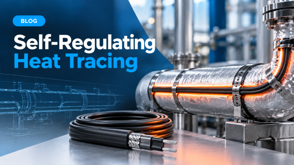
A Freeze Night That Started With One Wrong Cable
The call came at 2 a.m. from a water treatment plant. A twenty-metre run of instrument tubing had frozen solid, and the self regulating heat tracing wrapped around it was warm to the touch along the first five metres and stone cold after that. The cable had not failed. It had been specified for a pipe temperature the line never actually reached, and the polymer core had throttled its own output down to almost nothing.
That is the quiet failure mode of self regulating heat tracing. Nothing burns out, no breaker trips, and the maintenance log stays clean until the night the line freezes.
Constant wattage cable fails loudly. Self regulating cable fails by doing exactly what its physics tells it to do, at a temperature nobody calculated for. The same pattern turns up across industrial heating and process applications, where a specification error looks like an equipment failure for months. The rest of this piece covers what to specify, what to measure, and how to diagnose the symptoms that look like cable faults but are usually specification mistakes.
What Self Regulating Heat Tracing Actually Controls
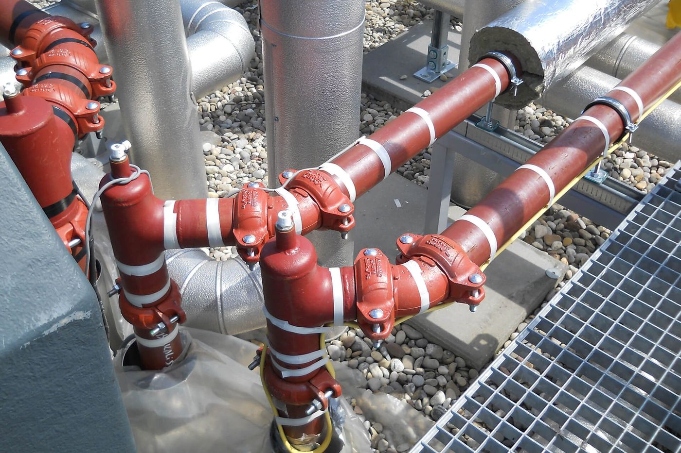
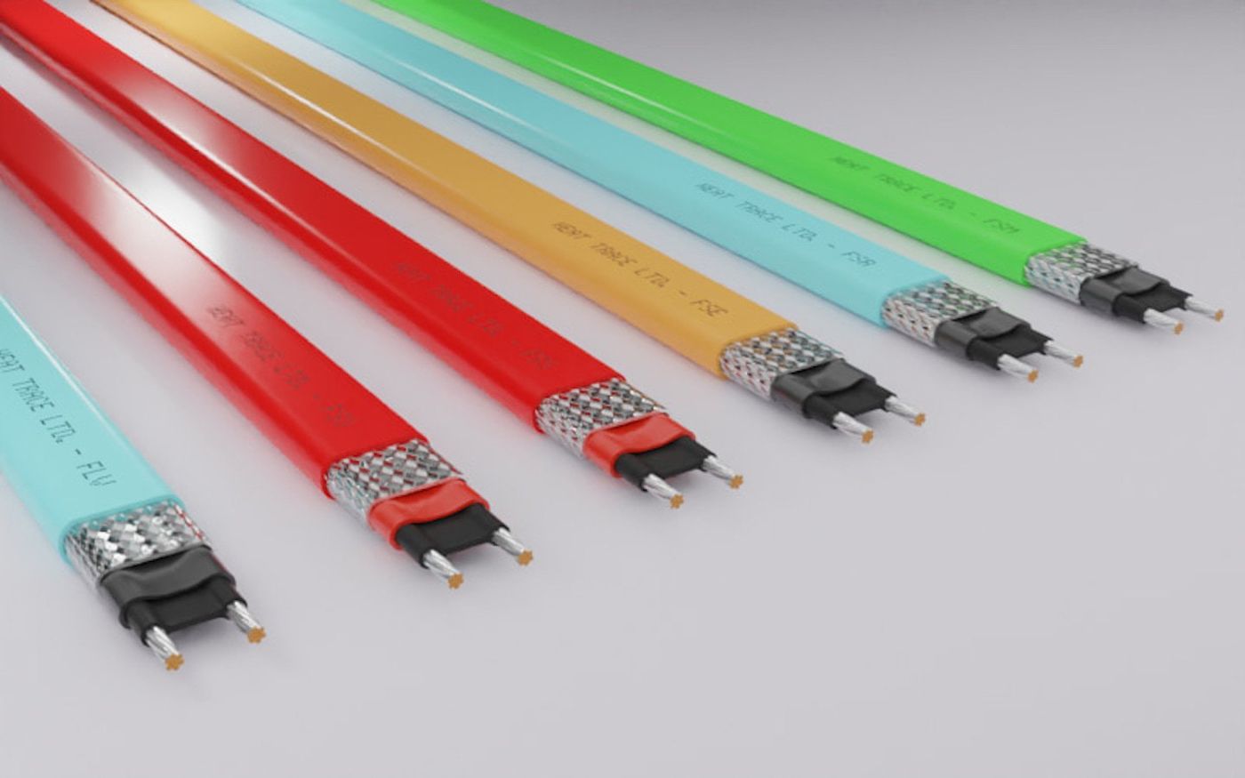
Self regulating heat tracing uses a conductive polymer core between two bus wires. As the cable warms, the polymer expands and its resistance rises, so current falls. Output drops without any controller involvement. As the pipe cools, the reverse happens and output climbs back.
That behaviour makes the cable safe to overlap and safe to cut to length on site. Self regulating heat tracing also means the output figure printed on a datasheet applies to one specific pipe temperature, and no other. Ask for the output at the wrong temperature and you will buy a cable that cannot hold your line.
Three duties dominate industrial applications. Freeze protection keeps water lines above zero. Process maintenance holds a fluid at a target band, often between twenty and eighty degrees Celsius. Viscosity control keeps heavy products moving through transfer lines.
Each duty sets a different temperature target, and self regulating heat tracing is specified against that target rather than against a wattage alone. Getting the duty wrong is the first and most expensive mistake.
How the Cable Decides Its Own Output
Output falls as temperature rises because the core's resistance climbs. A cable rated at thirty watts per metre at ten degrees Celsius may deliver only fifteen watts per metre at sixty degrees Celsius. The curve is not linear, and it is not the same between manufacturers. Self regulating heat tracing therefore carries a different output specification for every duty it serves.
Two consequences follow. First, a specification written as a single wattage figure is meaningless without the temperature attached. Second, cable selection for a hot process line cannot assume the cold output figure at all.
A practical rule from field experience: if the required maintain temperature sits above half of the cable's maximum continuous exposure rating, go up one output class and recheck the curve rather than accepting the first option that meets the cold figure.
Manufacturers publish those curves because self regulating heat tracing cannot be selected from a single number. Where a project lacks a curve, request one in writing before the cable is ordered.
Control hardware matters here too. Where a line needs a tight band, the tracing works alongside a controller that reads pipe temperature and switches zones, and a modular temperature controller architecture scales the same way when a panel grows from four zones to forty. The same principles used on a hot runner temperature controller apply to heat trace panels, with one difference: the cable already limits itself, so the controller is trimming rather than protecting.
Reading a Watt Density Curve Before You Buy
A watt density curve plots output against pipe temperature for a given cable construction. Read it at your maintain temperature, then apply the correction factors that the curve itself does not include.
Voltage derating comes first, and it belongs in every calculation for self regulating heat tracing. Most curves are drawn at nominal voltage. A site running five percent low loses roughly ten percent of output on a resistive load, and self regulating cable behaves in the same direction.
Insulation comes second, and it is the biggest lever. A well insulated line can need less than half the wattage of a bare one. Skipping insulation to save capital cost is the fastest way to turn a workable design into a marginal one.
Ambient temperature comes third. Cable running through an unheated outdoor tray starts colder and pulls a higher inrush current at start-up, which affects breaker selection more than it affects steady-state performance.
Finally, count the passes. Two parallel runs of a lower-output cable often beat one run of a high-output cable, because heat spreads more evenly around the pipe circumference and the surface temperature stays lower. This is one of the few places where self regulating heat tracing lets you trade cable quantity against cable class.
Specification Table: The Numbers to Fix Before Ordering
Ordering goes wrong when a specification leaves a number open. Self regulating heat tracing projects fail this way more often than they fail on cable quality. The table below covers the figures worth fixing in writing before a purchase order exists.
Market analysts tracking the self regulating heat trace cable market note the shift toward polymer-core cable across industrial and commercial sectors, which makes specification discipline more valuable rather than less.
| Parameter | Unit | Typical figure | Why it matters |
|---|---|---|---|
| Maintain temperature | °C | 5 for freeze protection, 20 to 80 for process | Sets the point on the watt density curve where the cable must still deliver |
| Cable output at maintain temperature | W/m | Read from the curve, never from the headline rating | The headline figure is quoted at a lower temperature than most process lines reach |
| Maximum continuous exposure | °C | 65 to 200 depending on construction | The power-off limit the jacket and core can survive without degrading |
| Supply voltage | V | 230 or 400 to 480 three phase | Voltage sag cuts output, so a marginal design fails on a bad grid day |
| Insulation thickness | mm | 25 to 75 on process pipework | Drives heat loss and therefore the wattage the cable has to replace |
| Start-up current | A per metre | Two to four times steady state when cold | Sizes the breaker and the panel, and it is the figure most often omitted |
| Zone length | m | Set by breaker rating and voltage drop | Long single runs lose voltage at the far end and underperform there |
| Overjacket and braid | Type | Fluoropolymer with tinned copper braid for hazardous areas | Mechanical and chemical protection, plus the earth path a braid provides |
The start-up current row causes the most site problems. Self regulating cable draws a large inrush when cold, and the figure rises with ambient. Panels sized on steady-state current trip on the first cold morning of the year, and the fix is a breaker and cable schedule that were right from the start.
Document the same figures for every zone, because maintenance crews inherit the paperwork rather than the design conversation. A line without a cable schedule is a line that gets repaired by guesswork.
Insulation, Ambient and the Derating Trap
Derating is where self regulating heat tracing designs quietly fail. Three effects compound.
High pipe temperature reduces cable output through the polymer core, as described earlier. High ambient temperature does the same thing from the outside. Voltage below nominal cuts it a third time.
A design that passes on paper at nominal voltage in a mild climate can miss its maintain temperature by ten degrees in a hot plant room on a low-voltage afternoon. Self regulating heat tracing has no way to compensate for that once the cable is installed. The remedy is unglamorous. Add margin at the specification stage rather than hoping the site behaves like the datasheet.
Insulation condition belongs in the same conversation. Wet or damaged insulation raises heat loss dramatically, and a line that held temperature with dry insulation may not hold it after a steam-out or a washdown. Self regulating heat tracing compensates a little by raising output as the pipe cools, but the compensation has a ceiling.
Where the ceiling matters, instrumentation closes the gap. A mould temperature controller is built for a different duty, yet the sensing and switching logic behind it is the same discipline that keeps a heat trace zone honest: measure the surface, act on the measurement, and alarm when the reading stops moving.
A Commissioning Sequence That Catches Most Faults
Commissioning finds problems that specification review cannot. The IEC standards for electrical installations and the site's own classification drawings set the framework; the sequence below is what actually finds faults.
Step one: visual and mechanical. Confirm no cable is crushed, kinked, or installed over a sharp edge. Self regulating heat tracing tolerates overlap, but it does not tolerate a nick through the jacket or a tie wire pulled tight enough to cut into the braid.
Step two: insulation resistance. Megger each circuit to earth and between bus wires before applying power. Values that drift between the factory test and site are the earliest sign of moisture ingress.
Step three: continuity and circuit length. Verify that the measured resistance matches the expected length for the cable type. A short read usually means a damaged section or a splice that was not made correctly.
Step four: energise and measure surface temperature. Thermography along the run shows whether output is even. Cold spots at the far end point to voltage drop, not to a cable fault.
Step five: verify control response. Force the controller above and below setpoint and confirm the contactor or solid state relay follows. A zone that never switches is a zone that will freeze without warning.
Step six: document and hand over. Cable type, length, voltage, megger values, and zone schedule belong in a file that the maintenance team can find at three in the morning.

Fault Diagnosis: Six Symptoms and Their Real Causes
Most heat trace callouts look like cable failures and turn out to be something else. Self regulating heat tracing has a narrow set of component-level failure modes and a wide set of system-level ones. Work through the symptoms in order before ordering replacement cable.
The circuit trips the breaker on a cold morning. Start-up current exceeded the breaker rating. Check the cold resistance and the panel schedule before blaming the cable.
The whole circuit is cold and the breaker is up. Control circuit problem, or a contactor that has failed closed with a burnt coil. Verify voltage at the far end of the run, not at the panel.
The first metres are hot and the tail is cold. Voltage drop on a long run, or a damaged section where a splice was made. Measure voltage at the tail under load.
The zone holds temperature in mild weather and loses it in summer. Derating has been exceeded. The cable is behaving correctly and the design margin was never there.
Megger readings fall every quarter. Moisture is entering, usually at a termination or an unsealed junction box. Self regulating heat tracing is unforgiving about water in the wrong place.
The zone cycles faster and faster over months. Insulation has absorbed moisture or been damaged, so heat loss has risen and the controller is fighting a losing battle. Fix the insulation before replacing anything electrical.
One pattern ties these together. Self regulating heat tracing rarely fails as a component. It fails as a system, and the system includes insulation, terminations, panels, and documentation.
Timeline: From Specification to Handover
Heat trace projects run on a predictable sequence. Knowing the order prevents the classic problem of cable arriving after the insulation is already closed up.
| Stage | What happens | What goes wrong if skipped |
|---|---|---|
| Duty definition | Maintain temperature and ambient range fixed in writing | Cable selected against the wrong point on the output curve |
| Heat loss calculation | Line loss computed from pipe size, insulation and ambient | Wattage chosen by habit rather than by arithmetic |
| Cable and panel selection | Output class chosen at maintain temperature, breaker sized on cold inrush | Nuisance tripping on the first cold start |
| Isometric and cable schedule | Zone lengths, terminations and junction box positions drawn | Field crews improvise runs and exceed zone limits |
| Installation | Cable laid before insulation closes, allowances for valves and flanges | Retrofit work through finished insulation at triple the cost |
| Insulation and cladding | Thermal insulation fitted over the traced pipe | Output requirement doubles on an uninsulated run |
| Commissioning | Megger, continuity, energise, thermography, control check | Faults surface during the first freeze instead of before handover |
| Handover file | Cable schedule, test values and zone map delivered to maintenance | Next repair becomes guesswork |
The installation row carries the largest commercial risk. Self regulating heat tracing is cheap to install while a line is open and expensive to install afterwards. Sequencing it after insulation means cutting cladding, working around lagging, and re-sealing everything afterwards.
Controls and Sensors That Keep Self Regulating Heat Tracing Honest
A cable that limits its own output still needs supervision. Unsupervised zones give no warning before a freeze event, and the failure appears as a process problem rather than an electrical one.
Line sensing suits process maintenance. A sensor measures pipe or product temperature and switches the circuit. Ambient sensing suits freeze protection, where the risk is driven by air temperature rather than by what is in the pipe. Control hardware for either duty follows the same pattern as the touch screen temperature controllers used on multi-zone process panels.
Sensor choice matters more than controller brand. A clamp-on sensor reads pipe skin temperature and responds quickly. A sensor in a thermowell reads product temperature and responds slowly. Both are legitimate, and using one where the other belongs produces either short cycling or sluggish response.
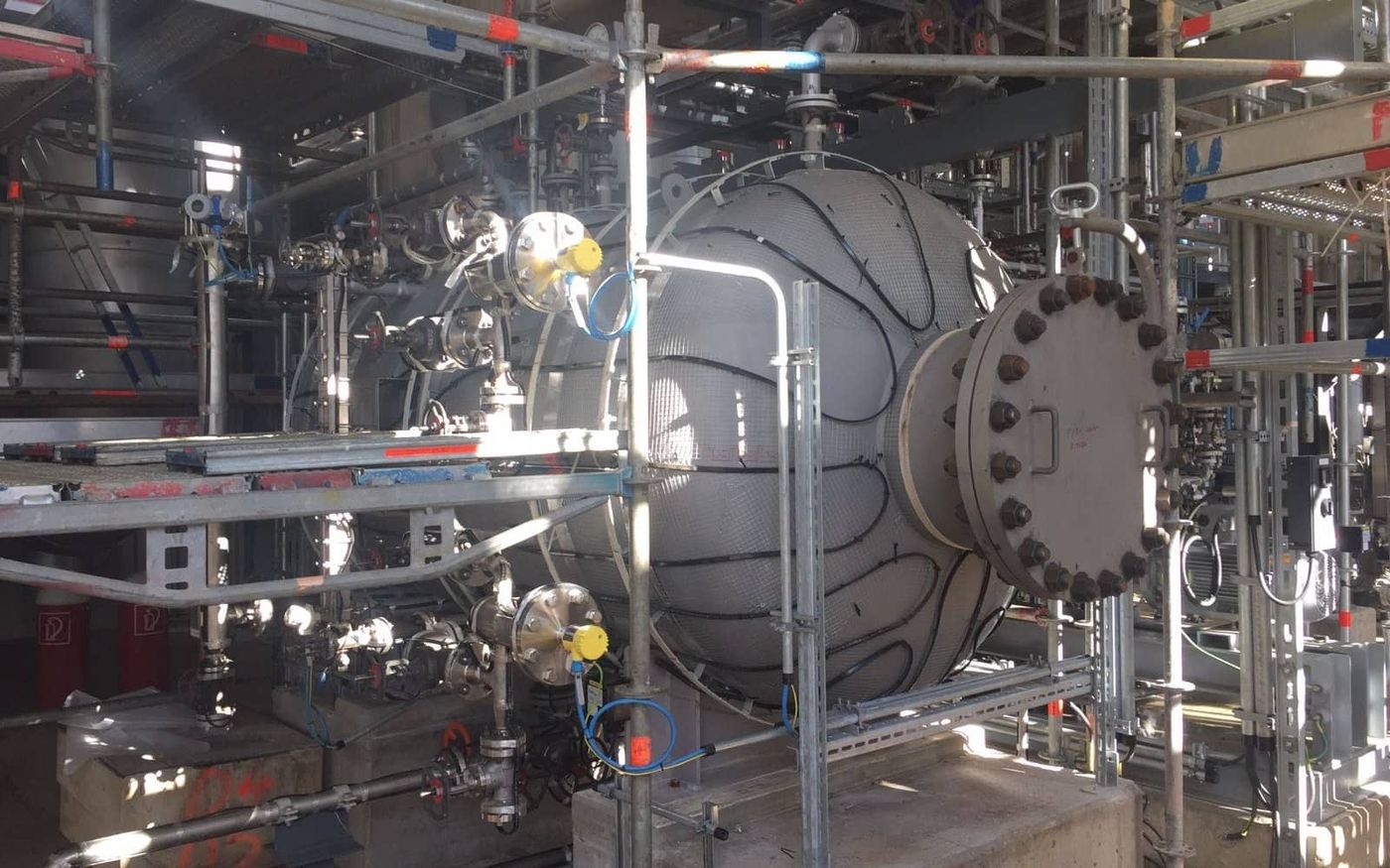
The sensing chain has its own hardware needs, and the same components that keep a controller accurate apply here. RTDs, thermocouples and the wiring between them belong in the same specification conversation as the hot runner controller accessories that engineers already buy for mould temperature work. A sensor reading that drifts by five degrees is worse than no sensor, because it looks trustworthy.
Alarm strategy finishes the design. Each zone should raise an alarm on low temperature rather than only on circuit failure. A cable can be energised, drawing current, and still losing ground against a cold wind if the insulation is wet.
For high-consequence lines, add a second independent sensor and alarm on disagreement. Self regulating heat tracing is reliable, but a line feeding a critical process deserves verification rather than trust.

Frequently Asked Questions
Can self regulating heat tracing cable be cut to length on site?
Yes. That is one of its advantages over constant wattage cable, and it means site alterations do not require a factory re-order. Terminate properly, seal against moisture, and record the new length in the cable schedule.
Why does my cable deliver less heat than the datasheet says?
Because the datasheet figure is quoted at a lower temperature than your pipe reaches. Read the watt density curve at your actual maintain temperature, then apply corrections for voltage, insulation condition and ambient. The gap is usually substantial.
Is self regulating heat tracing suitable for hazardous areas?
Yes, with the correct construction. Braided and overjacketed cable plus suitably rated junction boxes and glands are the usual combination. Follow the area classification for the site and confirm the cable carries the relevant certification.
How long should a single heating circuit run?
Set by breaker rating and acceptable voltage drop rather than by a fixed number. Long runs lose voltage at the tail, so the far end underperforms even when the near end looks perfect. Split long lines into zones instead of extending one circuit.
Can I overlap self regulating heat tracing cable?
Overlap is allowed and often useful at valves and flanges, because the cable reduces its own output where it gets hot. That self-limiting behaviour is what makes overlap safe on this cable type and unsafe on constant wattage types.
How often should heat trace circuits be tested?
Megger and continuity at commissioning, then on a scheduled interval tied to plant shutdowns. Trend the values rather than judging each reading alone, because a slow decline in insulation resistance is the earliest reliable warning of moisture ingress.
What maintain temperature should I specify for freeze protection?
Five degrees Celsius is the common target, which gives margin above zero without wasting energy. Where the fluid is sensitive or the pipe runs exposed to wind, raise the target and recalculate the heat loss rather than assuming the standard figure covers it.
Handing Over a Line You Can Trust
Self regulating heat tracing rewards a short list of disciplines. Define the duty in writing. Read the output curve at the maintain temperature rather than at the headline rating. Add margin for voltage, ambient and insulation condition. Size the panel on cold inrush. Commission with measurements and hand over a cable schedule.
None of that is technically difficult. All of it is easy to skip, and every skipped step shows up on a cold night somewhere down the line.
Sensors, controllers and the hardware that keeps heat trace zones honest come from the same engineering family as the temperature control products we build for mould and process work, and they are specified with the same quality and capability discipline. If a line needs its control chain reviewed end to end, talk to our engineering team before the cable schedule is frozen.