
Table of Contents
- What Is Text Milling?
- How Text Milling Works
- Applications in Mold Making
- Text Milling vs. Laser Engraving vs. Chemical Etching
- Step-by-Step Text Milling Process
- Key Considerations for Quality Results
- Cost Factors to Consider
- Industries and Use Cases
- Frequently Asked Questions
What Is Text Milling?
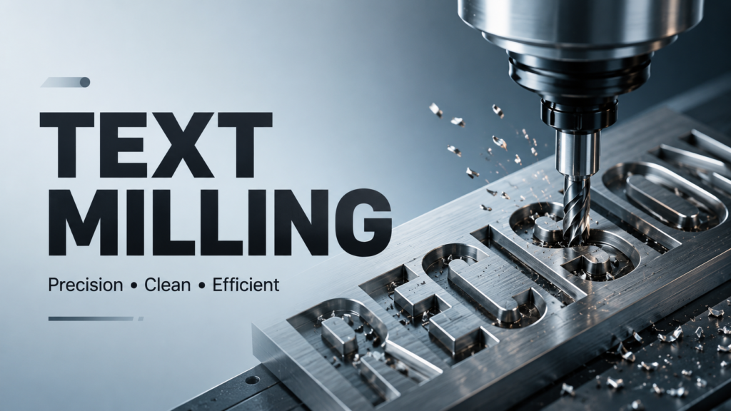
Text milling is a CNC machining process that uses rotating cutting tools to engrave letters, numbers, symbols, and logos onto metal surfaces. Unlike standard milling that removes large amounts of material for shaping parts, text milling focuses on creating shallow, precise grooves that form readable characters. The term is sometimes used interchangeably with CNC engraving, though text milling typically refers specifically to industrial marking applications rather than decorative work.
For manufacturers working with injection molds, dies, and tooling, text milling is the go-to method for adding permanent identification marks. Part numbers, date codes, cavity numbers, company logos, and serial numbers are all commonly produced using this technique. A typical hot runner system might have dozens of components that need individual identification, and text milling provides the durability those marks require.
The process works on a standard CNC milling machine equipped with a small-diameter end mill — typically 0.1 mm to 2.0 mm. The tool follows a programmed path that traces each character's outline or fills its interior. The result is a durable, wear-resistant mark that lasts as long as the tool itself. Unlike adhesive labels that peel off or ink stamps that fade, milled text becomes part of the metal surface.
What sets text milling apart from simple engraving is the level of control. Depth, width, surface finish, and font style can all be adjusted within the CAM (Computer-Aided Manufacturing) software. That makes it suitable for both functional marks — like serial numbers that need to be read by barcode scanners — and aesthetic marks like brand logos on visible surfaces of the final product.
Definition aside, text milling sits at the intersection of precision machining and marking technology. It delivers repeatability that hand stamping cannot match and durability that ink-based marking cannot offer. For shops already running CNC facing milling operations, adding text milling capability requires minimal additional investment — just the right tooling and CAM programming knowledge.
How Text Milling Works
Text milling relies on the same core principles as conventional CNC milling, with a few key differences in tooling and programming. Understanding these differences helps operators avoid common mistakes and achieve clean results consistently.
The Tooling
Ball end mills or flat end mills with small diameters handle the engraving work. Carbide tools are standard — they hold an edge longer and resist deflection when cutting hardened materials. For mold steels (typically 30-52 HRC), coated carbide tools with TiAlN or AlTiN coatings extend tool life significantly. Uncoated tools work fine for aluminum and brass but wear quickly on steel.
Tool selection depends on character size. A 0.3 mm end mill suits very small text (1-2 mm character height). For standard mold markings in the 3-6 mm range, 0.5-1.0 mm tools offer the best balance of detail and cycle time. Larger tools (2.0 mm+) work for big characters on mold bases and support plates.
The Program
A CAM program converts the desired text into tool paths. Each character gets translated into a series of moves — linear moves for straight segments, arc moves for curves, and stepovers for area milling if the character gets filled rather than just outlined. Modern CAM systems like Fusion 360, Mastercam, or SolidCAM include dedicated engraving cycles that simplify this step. Some even auto-generate cutter compensation to maintain character width when tools wear.
The Machine
Any rigid CNC mill can perform text milling — VMCs (vertical machining centers), CNC routers, and even 5-axis machines. The critical requirement is spindle speed. Small engraving tools need high RPM (10,000-30,000) to achieve proper surface speed. Machines with lower spindle speeds may produce rough finishes or cause tool breakage. For reference, a 0.5 mm end mill at 12,000 RPM achieves a surface speed of about 19 m/min — barely adequate for steel. At 20,000 RPM the same tool reaches 31 m/min, which produces noticeably better finish and longer tool life.
For mold text milling specifically, a 3-axis VMC with a 15,000 RPM or higher spindle handles most jobs. The mold gets secured on the table, the text program gets loaded, and the machine runs the cycle unattended. This makes text milling compatible with lights-out manufacturing approaches common in modern shops.

Coolant and Chip Control
Small end mills generate fine chips that pack into the cut zone. Air blast directed at the cutting area is the preferred method for chip evacuation. Flood coolant can work but may cause tool deflection on very small tools. For hardened steels, a mist coolant system provides enough lubrication without the hydraulic forces of flood coolant.
Applications in Mold Making
Text milling plays a practical role in injection mold manufacturing. Here is where it shows up most often, and why each application benefits from milling over alternative marking methods.
Cavity Numbering
Multi-cavity molds need each cavity identified so production teams can trace defects back to a specific cavity. Text milling creates permanent cavity numbers (Cav 1, Cav 2, Cav 3, and so on) directly on the mold plate. Unlike adhesive labels or ink stamps, these numbers survive mold maintenance, polishing, and thermal cycling. In molds with 16, 32, or even 64 cavities — common in packaging and cap production — clear cavity numbering is essential for quality control. The applications page shows examples of multi-cavity setups used in bottle cap and packaging production.
Date Code Inserts
Many molds include replaceable date code inserts that get updated periodically. Text milling produces the raised or recessed date characters on these inserts. The marks transfer to every molded part, giving manufacturers a way to track production dates without separate labeling. Date codes also help with batch recall management and warranty verification.
Part Number and Logo Marking
Mold bases, slides, lifters, and core pins often carry part numbers or customer logos for identification during assembly and maintenance. Text milling creates these marks with consistent readability across all components. For OEM mold builders who supply to multiple customers, clear logo marking helps prevent mix-ups during assembly and shipping.
Serial Number Engraving
High-value molds are serialized for warranty tracking and maintenance records. Text milling creates permanent serialization that resists wear from handling, cleaning, and storage. Serial numbers also aid in resale value — documented serialization proves the mold's production history and maintenance schedule. A mold temperature controller record paired with serialized mold data helps operators maintain consistent process conditions across production runs.
Hot Runner Component Labeling
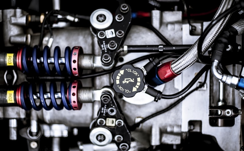
For hot runner systems specifically, cavity identification marks help operators match temperature controller zones to the correct cavities. Manifold blocks, nozzle holders, and distribution plates all benefit from clear text marking. Without it, troubleshooting zone-to-cavity mapping becomes guesswork. This is where text milling connects directly to temperature control — each zone label on the manifold needs to stay legible through hundreds of thousands of cycles, and milling ensures it does.
Text Milling vs. Laser Engraving vs. Chemical Etching
Text milling is not the only way to mark metal. Here is how it compares to the two most common alternatives so you can choose the right method for your application.
| Factor | Text Milling | Laser Engraving | Chemical Etching |
|---|---|---|---|
| Depth control | Excellent — adjustable from 0.05 mm to 1.0 mm+ | Limited — typically 0.01-0.1 mm | Limited — typically 0.01-0.05 mm |
| Equipment cost | Low to medium — uses existing CNC mill | High — fiber laser system $20k-$80k | Low — chemical consumables only |
| Durability | High — survives polishing and thermal cycling | Medium — shallow marks may wear on high-wear surfaces | Low — shallow etch wears quickly in mold use |
| Font flexibility | Any CAM-supported font or custom geometry | Vector-based fonts only | Mask-dependent; limited resolution |
| Surface prep needed | Minimal — clean surface sufficient | Clean surface; reflective surfaces harder | Extensive — cleaning, masking, etching, neutralizing |
| Cycle time (per character) | 5-15 seconds | 1-5 seconds | 30-60 minutes per batch |
| Typical mark depth | 0.1-0.5 mm | 0.01-0.05 mm | 0.01-0.03 mm |
| Secondary deburring | Usually required | Not required | Not required |
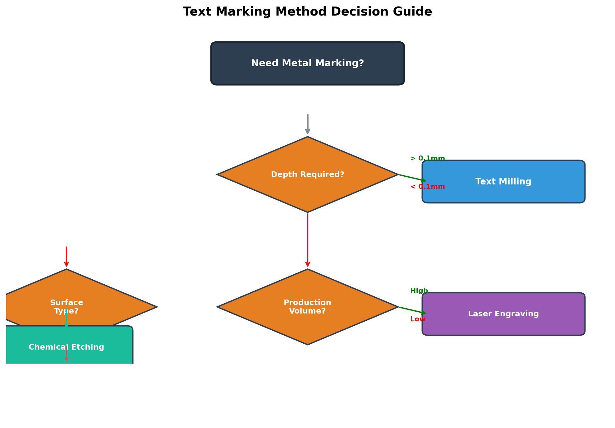
For mold marking applications where depth and durability matter most, text milling remains the preferred method. Laser engraving works well for shallow, high-speed marking on flat surfaces. Chemical etching suits large-area texturing but is rarely used for individual text marks due to the lengthy process time and environmental handling of etching chemicals.
Step-by-Step Text Milling Process
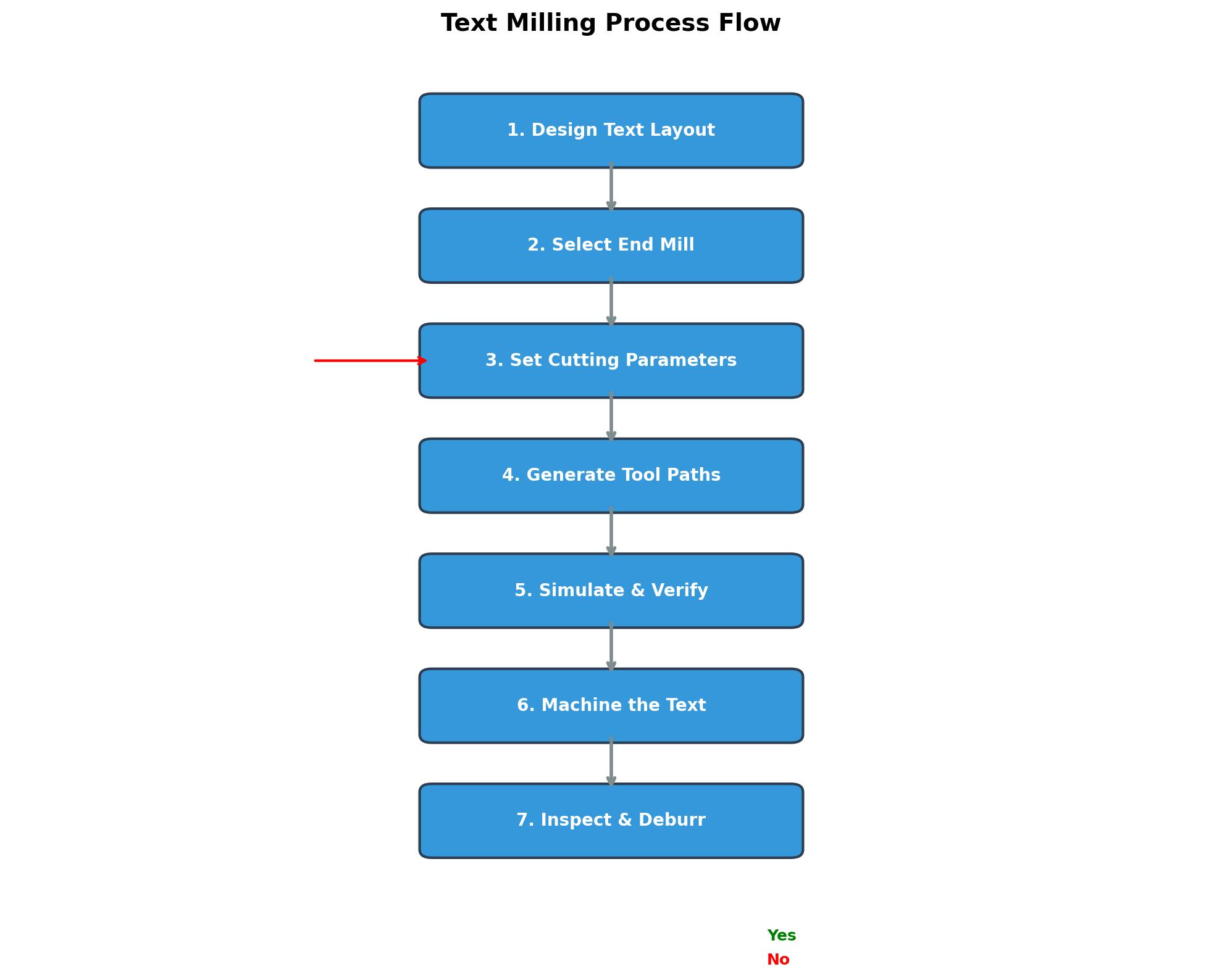
Here is the typical workflow for adding text to a mold component. Following these steps consistently produces clean, professional results.
Step 1: Design the Text Layout
Define the text content, font style, character height, and position on the part surface. Use the CAM software sketching tools or import DXF artwork. Keep character height above 1.5 mm for readability — smaller characters risk being unreadable after mold polishing. For raised text (bossed characters), plan for additional stock around each character.
Step 2: Select the Tool
Choose a carbide end mill sized to the smallest feature. A 0.5 mm ball end mill works for text 2-3 mm tall. For larger text, 1.0 mm or 2.0 mm tools remove material faster. Stepped characters (raised text) need more clearance than incised (recessed) characters. For the best surface finish in mold steel, use a ball end mill rather than a flat end mill.
Step 3: Set Cutting Parameters
Typical starting parameters for text milling in P20 or H13 mold steel: spindle speed 12,000-18,000 RPM, feed rate 500-1,000 mm/min, depth per pass 0.05-0.15 mm. Adjust based on material hardness and tool diameter. Softer materials like aluminum allow higher feed rates — up to 2,000 mm/min with proper chip load. Harder materials (above 45 HRC) require reduced feeds and multiple shallow passes.
Step 4: Generate Tool Paths
Use the CAM engraving cycle to generate paths. Two common strategies exist: outline milling (follows character contours) and pocket milling (fills the character area). Outline milling is faster and typically sufficient for small text. Pocket milling gives a more pronounced appearance and works better for logos or large characters where visual impact matters.
Step 5: Simulate and Verify
Run CAM simulation to check for collisions, excessive cutting forces, or incomplete characters. Verify that the text fits within the marked area and that depth across all characters stays uniform. Simulation also catches tool holder collisions with nearby cavity details.
Step 6: Machine the Text
Secure the workpiece, set the Z-zero reference on the top surface, and run the program. Use coolant mist or air blast for chip evacuation — small tools clog easily if chips recut. For mold text milling on hardened steel, climb milling produces better surface finish than conventional milling. Reduce stepover distances for filled characters to minimize visible tool marks.
Step 7: Inspect and Clean
Check character depth with a depth micrometer or optical comparator. Remove burrs with a fine stone or rubber abrasive wheel. For mold cavities, verify that the text stands out clearly and does not interfere with the molding surface. Document the cutting parameters used so the same settings can be replicated for future jobs.
Key Considerations for Quality Results
A few factors separate clean, professional text milling from rough, unreadable marks. Pay attention to these details and the results improve noticeably.
Tool runout. Even 0.01 mm of runout at 15,000 RPM produces inconsistent character width. Use a precision collet or shrink-fit holder for small engraving tools. Hydraulic chucks offer the best runout control but cost more. For most shops, an ER collet with a runout under 0.005 mm is adequate for text down to 1.5 mm character height.
Chip evacuation. Small end mills generate fine chips that pack into the cut zone. Air blast directed at the cutting area prevents chip re-cutting, which is the leading cause of tool breakage in text milling operations. Position the air nozzle so it blows chips away from the cut, not into it.
Material hardness variation. Mold steels often have hardened surfaces from EDM or heat treatment. If the text area has inconsistent hardness, the tool may deflect, producing variable depth. Pre-machining the surface to a uniform condition helps, as does using a slightly larger tool that can handle hardness variations without deflection.
Character legibility after polishing. Mold cavities get polished during production. Text that is too shallow (under 0.1 mm) may become unreadable after two or three polishing cycles. For production molds, aim for 0.2-0.3 mm minimum depth. For high-wear areas or molds that undergo frequent reconditioning, 0.5 mm depth is recommended.
Font selection. Sans-serif fonts like Arial or Helvetica produce the cleanest text milling results. Serif fonts with thin strokes may lose definition at small sizes. For serial numbers and date codes, single-stroke fonts (stick fonts) machine faster and stay legible longer. Avoid script or decorative fonts unless the application specifically requires them.
Cost Factors to Consider
Text milling costs depend on several variables. Understanding them helps with budgeting and method selection. Here is a breakdown of typical cost drivers.
| Cost Driver | Impact Range | Notes |
|---|---|---|
| Setup time | $30-$80 per job | Programming, fixturing, tool selection |
| Machine time | $0.50-$2.00 per character | Depends on character size and depth |
| Tooling | $8-$25 per end mill | Small tools wear faster; carbide preferred |
| Material hardness surcharge | +15% to 30% | Hardened steel vs. pre-hardened or aluminum |
| Inspection | $10-$25 per part | Depth and legibility verification |
| Deburring | $5-$15 per part | Manual or automated edge break |
For a typical mold cavity with 6-8 characters, expect total cost in the $50-$150 range. Compare that to laser engraving ($30-$80) — the difference narrows when durability requirements demand deeper marks that only milling can achieve. For molds that will run for years, the additional upfront cost of text milling pays for itself through reduced re-marking and replacement.
Industries and Use Cases
Text milling serves a broad range of manufacturing industries beyond injection mold making. Understanding these use cases helps justify the investment in text milling capability.
Automotive
Engine blocks, transmission housings, and brake components all carry identifying marks. Text milling produces deep, durable marks that survive the harsh conditions of automotive use — heat, vibration, and exposure to oils and coolants. Many Tier 1 suppliers specify milled text marks in their quality documentation.
Aerospace
Aerospace manufacturers need traceable serialization that withstands extreme temperature cycles and aggressive cleaning solvents. Text milling on titanium and nickel alloys creates marks that remain readable through the entire service life of the component. The FAA and EASA require permanent marking on many flight-critical parts, and text milling meets those requirements.
Medical Device Manufacturing
Medical molds and surgical instruments require marks that survive repeated sterilization cycles. Autoclaving, chemical sterilization, and gamma irradiation can fade ink marks or delaminate adhesive labels. Text milling produces marks that are unaffected by any of these sterilization methods.
General Precision Engineering
For general CNC precision machining, text milling adds value by embedding identification directly into components during the machining process. This eliminates the need for a separate marking operation, reducing handling and cycle time. Shops that combine text milling with their regular machining workflow gain a competitive advantage in turnaround time.
Frequently Asked Questions
Can you text mill on hardened mold steel?
Yes. Carbide end mills with TiAlN coating handle hardened steel up to 52 HRC. Reduce feed rate by 30-40% compared to pre-hardened material. Use shallow depths per pass (0.03-0.08 mm) to avoid tool deflection. For materials above 52 HRC, consider laser engraving as an alternative or use CBN (cubic boron nitride) tooling.
What is the smallest readable text size in text milling?
With a 0.2 mm end mill, characters as small as 0.8 mm tall are achievable on flat surfaces. For practical readability in mold applications, 1.5-2.0 mm is the recommended minimum. This is especially important if the mold undergoes regular polishing, as each polishing cycle removes a small amount of surface material.
Is text milling the same as CNC engraving?
Not exactly. CNC engraving typically refers to decorative or artistic marking with specialized engraving tools. Text milling uses standard milling cutters and machine tools, making it more suitable for industrial applications where durability and dimensional accuracy matter. The tooling, feeds, and speeds differ between the two processes.
How deep should text milling be for mold cavities?
For production molds, 0.2-0.3 mm depth is the standard target. This provides enough material to survive multiple polishing cycles without becoming unreadable. Deeper marks (0.5 mm+) may be needed for high-wear areas or if the mold sees frequent maintenance. Always test depth on a sample piece before committing to production molds.
Does text milling affect mold performance?
No, when done correctly. Text marks should be placed in non-critical areas of the mold — typically the back face, side surfaces, or ejector plate areas. Text on cavity surfaces can affect part appearance and is generally avoided. Proper depth control ensures the mark does not create stress concentration points.
Can text milling be automated for serial number marking?
Yes. With a probe to locate the workpiece and a macro program that increments the serial number, text milling runs unattended. Many mold shops use this approach for production molds that need sequential cavity numbering. The automation integrates easily with existing CNC workflows.
What file format is needed for text milling?
Most CAM systems accept DXF, DWG, or STP for text geometry. For simple text, the CAM built-in text tool is sufficient — no external file needed. For logos or custom graphics, vector DXF or AI files work best. Raster images (JPG, PNG) must be converted to vector format before they can be used for text milling.
Is text milling better than dot peen marking for serial numbers?
For applications requiring deep, clean characters that remain legible after polishing, text milling is better. Dot peen marking is faster but produces shallow dots that wear down faster. For permanent mold identification, text milling is the more reliable choice. Dot peen is better suited for flat, non-wearing surfaces where speed matters more than depth.
What spindle speed is required for text milling?
Minimum 10,000 RPM for small end mills under 1.0 mm. The ideal range is 15,000-24,000 RPM. Lower speeds cause poor surface finish and increased tool wear. If your machine maxes out at 8,000 RPM, larger characters (3 mm+) with bigger tools are more practical. Some shops retrofit high-speed spindles to their existing machines specifically for text milling work.
How do you remove burrs after text milling?
Fine-grit rubber abrasive wheels (320-600 grit) work well for deburring without altering character shape. For very small text, manual brushing with a brass wire brush is gentler. Avoid aggressive sanding that could reduce character depth. For production runs, tumbling or vibratory deburring can handle multiple parts simultaneously.
Can text milling be done on curved surfaces?
Yes. 4-axis and 5-axis CNC machines can text mill on curved surfaces by tilting the tool to maintain a consistent angle relative to the surface. 3-axis machines are limited to flat or gently curved surfaces where the tool can maintain proper engagement without interference.
How long do text milling tools last?
In pre-hardened P20 steel (30-32 HRC), a single carbide end mill typically produces 500-2,000 characters before requiring replacement. In hardened H13 (48-52 HRC), tool life drops to 200-500 characters. Coated tools last 30-50% longer than uncoated tools in both cases.
Summary
Text milling offers a reliable, durable method for adding permanent identification marks to metal components, especially in injection mold making and precision engineering. It requires standard CNC equipment, small carbide end mills, and proper CAM programming — all within reach for most manufacturing shops.
Compared to laser engraving and chemical etching, text milling delivers deeper, more durable marks that survive the demanding conditions of mold production. For cavity numbering, date code inserts, serialization, and logo marking, it remains the go-to process when permanence matters.
Shops already running CNC facing milling can add text milling capability with minimal additional investment. Combined with proper temperature control and a reliable hot runner controller, high-quality text marking completes the professional mold manufacturing process.
Need help configuring your mold temperature control setup? Contact TOPOWER for a practical quotation on modular or touch screen hot runner controllers.