
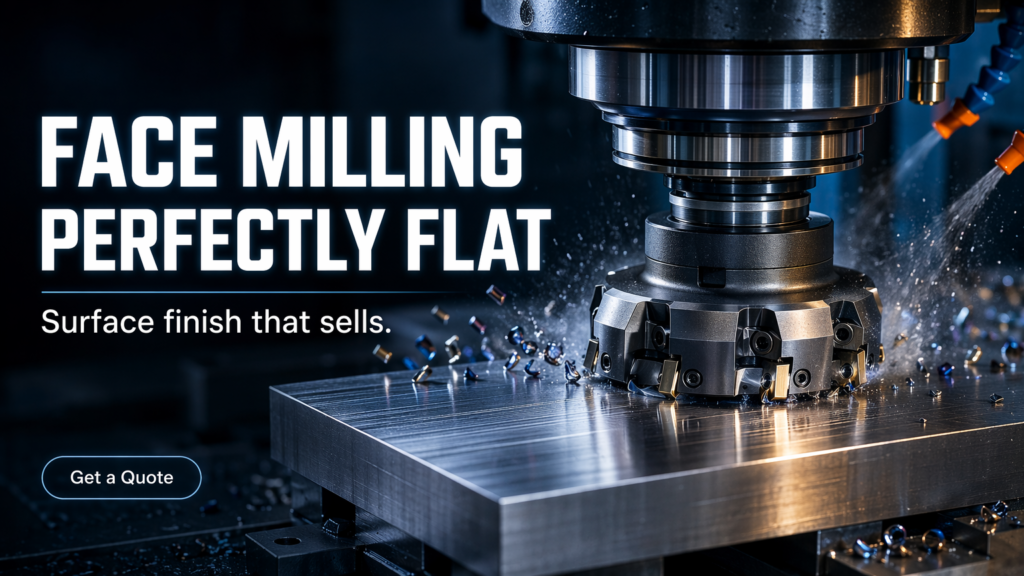
CNC facing or face milling is a machining operation designed to create flat surfaces precisely. It removes material across the top of a workpiece using a cutter with multiple teeth. This reliable process ensures superior flatness and surface finish, laying the critical foundation for subsequent manufacturing products and assembly steps.
What Is Facing (Face) Milling, Exactly?
Face milling involves a cutting tool whose rotational axis is perpendicular to the machined surface. Unlike other operations, the primary cutting action happens at the tool's periphery, while the face inserts generate the final smooth finish. This dual-action approach maximizes material removal efficiency.
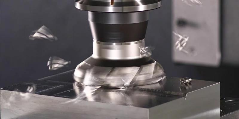
The difference between face and end milling lies in geometry and engagement. End milling cuts with both the bottom and sides, ideal for profiles and deep slots. Face milling primarily utilizes the bottom edges for broad horizontal cuts, making it unmatched for flattening large plates.
In a typical vertical machining center, face milling is often the very first operation. Establishing a true, flat reference plane is vital. Without this foundational accuracy, all subsequent tight-tolerance features and hole locations would be compromised.
Market Size (USD) and Why Face Milling Tracks These Markets
Face milling does not have an isolated market segment. Instead, its demand closely tracks the broader machine tool, milling machine, and CNC equipment markets. Understanding these macro sectors provides clear insight into the future demand for face milling solutions and related tooling.
| Market Segment | Market Size | Forecast | Source |
| Machine Tools | USD 81.09B (2025) | USD 105.11B (2032) | MarketsandMarkets |
| Milling Machines | USD 21.68B (2025) | USD 45.41B (2034) | Fortune Business Insights |
| CNC Machines | USD 66.74B (2022) | USD 132.93B (2030) | Grand View Research |
These robust figures indicate sustained global investment in manufacturing infrastructure. As automotive and aerospace sectors demand higher precision, the need for rigid CNC platforms capable of aggressive face milling naturally expands.
Consequently, cutting tool manufacturers and machine builders are focusing on high-feed strategies. The push for productivity in these multi-billion-dollar markets directly accelerates innovations in face milling insert materials and machine spindle designs.
From a global perspective with a strong China manufacturing lens, this growth is heavily fueled by Asia's robust industrial ecosystem. China remains a central hub for both machine tool production and consumption, driving supply chain dynamics and export manufacturing that dictate worldwide tooling demands.
Typical Applications and Where It Shows Up in Production
Face milling is fundamental across diverse manufacturing disciplines. In the automotive industry, it is essential for machining engine blocks and cylinder heads. Achieving a perfectly flat mating surface is non-negotiable for preventing fluid leaks and ensuring optimal engine compression.
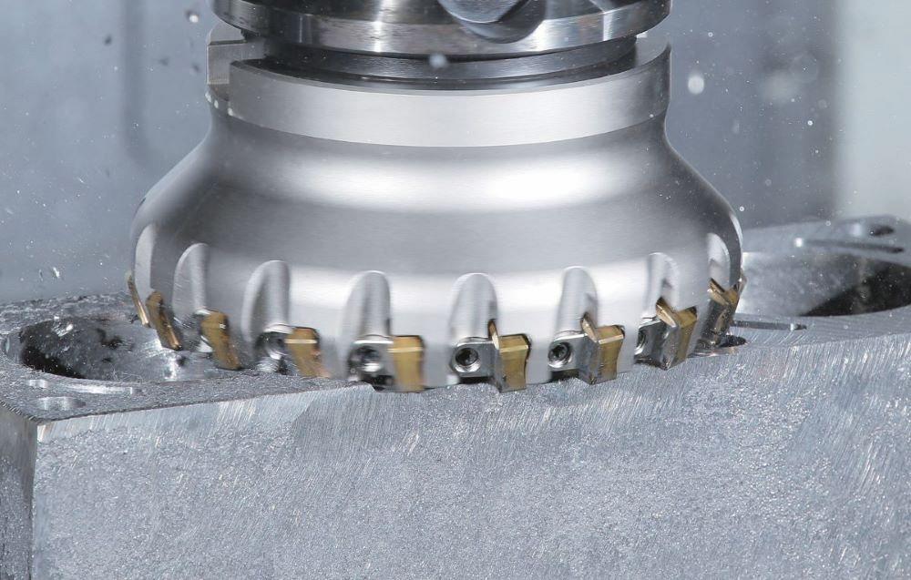
The aerospace sector relies heavily on this process to machine structural frames. When working with materials like 5083 aluminum, face milling rapidly removes bulk material while maintaining tight flatness tolerances, critical for lightweight yet rigid flight components.
In the tooling industry, producing high-precision mold bases and inserts requires extensive face milling. These foundational plates must be perfectly square and flat to ensure proper mold alignment and faultless injection molding cycles.
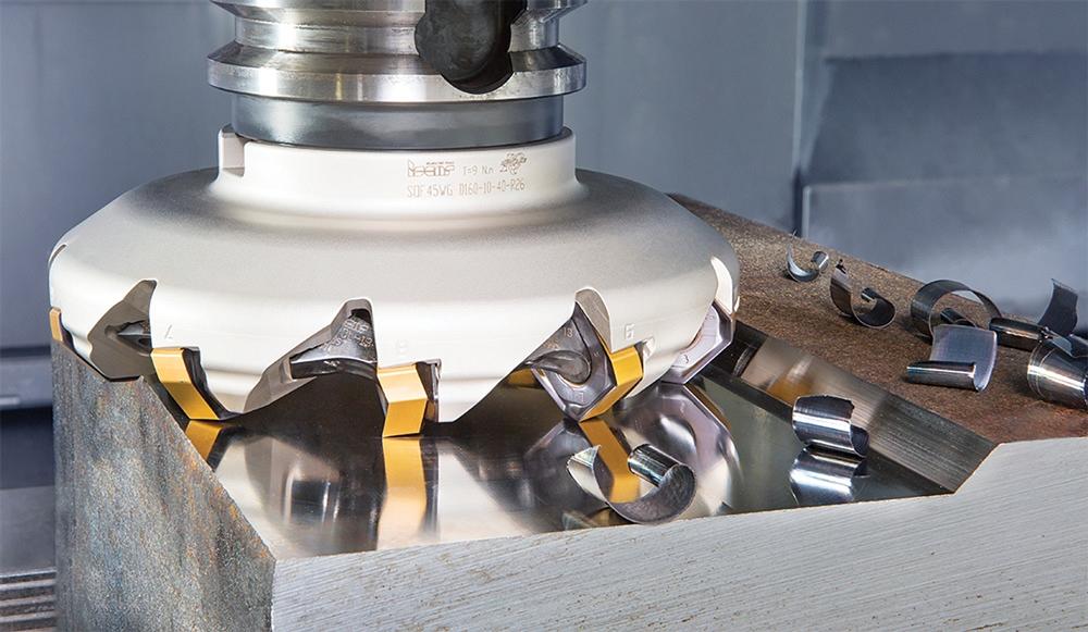
The technique is equally crucial for micro moulds, where even microscopic deviations in block flatness can cause flash or part failure. Precise facing guarantees that the parting lines seal flawlessly during high-pressure injection.
Finally, general job shops use face milling daily to prepare raw stock. Before any complex 3D contouring or precision hole-making can begin, machinists face mill fixtures and raw billets to establish reliable datum surfaces.
Typical Users and Buying Roles
CNC programmers and CAM engineers are the primary architects of face milling operations. They focus heavily on toolpath optimization and ensuring that spindle loads remain consistent. Their primary goal is maintaining process stability while maximizing material removal rates during continuous production runs.
Manufacturing and process engineers determine the broader production sequence. They are deeply concerned with cycle times, machine capability, and overall cost per part. They decide whether face milling or an alternative surface generation method best fits the project budget and timeline.
Production supervisors operate on the shop floor, managing daily throughput. They value predictability and tool life, as unexpected insert failures cause machine downtime. For them, reliable milling parameters ensure that production schedules are met without requiring constant operator intervention.
Sourcing and purchasing professionals handle the financial acquisition of machines and consumable inserts. They evaluate supplier reliability, bulk pricing, and lead times. Their objective is to secure the most cost-effective tooling solutions without sacrificing the performance required by the engineering team.
Quality control and maintenance teams ensure standards are upheld over time. Maintenance focuses on machine health and spindle wear, while quality engineers meticulously verify flatness and surface finish, often relying on strict quality capability metrics to validate the final output.
| Role | Primary Buying Criteria & Focus |
| CNC Programmers & CAM Engineers | Toolpath stability, software compatibility, tool life. |
| Manufacturing & Process Engineers | Cycle time optimization, process capability, cost per part. |
| Production Supervisors | Predictability, uptime, ease of insert replacement. |
| Sourcing & Purchasing | Supplier reliability, consumable costs, delivery lead times. |
| Quality & Maintenance | Surface finish consistency, dimensional accuracy, machine health. |
A Practical How‑To Workflow (From Print to Finished Face)
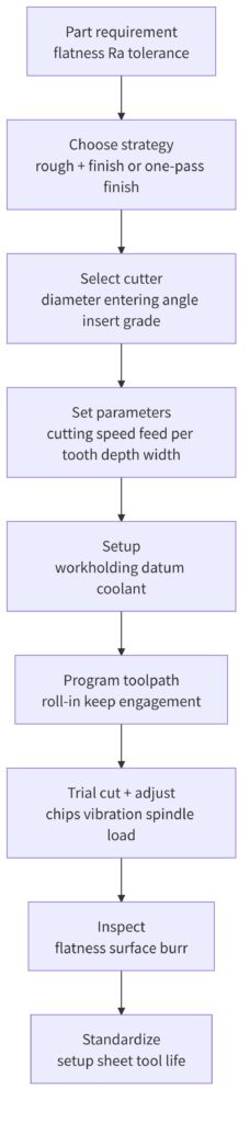
The first step is evaluating the print and material. Engineers must identify the required surface finish, flatness tolerance, and material hardness. This analysis dictates the entire approach, from rigidity requirements to selecting the correct cutting speeds and feeds.
Next is selecting the machine and spindle. Face milling demands significant horsepower and a rigid spindle taper. Engineers must verify that the chosen CNC machine can handle the cutting forces without inducing vibrations that would ruin the surface.
Choosing the cutter and inserts follows. Buyers select between 45-degree, 90-degree, or round insert cutters based on the application. The insert grade and coating are matched to the workpiece material to maximize tool life and material removal rates.
Programming the toolpath and parameters is critical for success. Software strategies like roll-in entry and maintaining constant cutter engagement prevent sudden shock loads on the inserts, ensuring smooth cutting action and extending the life of the tool.
Finally, execution and inspection close the loop. Operators run the program, often utilizing air blasts or coolant, and then verify the results. Profilometers and coordinate measuring machines confirm that the surface roughness and flatness meet the blueprint specifications.
Comparative Alternatives (When Face Milling Is Not the Best Answer)
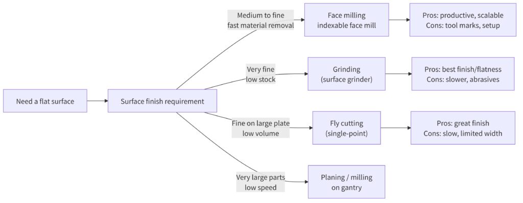
While highly versatile, face milling isn't always the optimal choice. When reviewing manufacturing applications, engineers must weigh throughput against extreme precision requirements to select the most cost-effective and capable surface generation method.
| Process | Surface Finish | Throughput | Equipment Cost | Best Fit Scenario |
| Face Milling | Good to Excellent | Very High | Moderate to High | General bulk material removal and standard flatness. |
| Fly Cutting | Exceptional (Mirror) | Low | Low (Tooling) | Ultra-fine finishes on non-ferrous materials. |
| Surface Grinding | Exceptional | Very Low | High | Hardened steels requiring extreme flatness and tight tolerances. |
| Planing / Gantry | Moderate | High (Large Parts) | Very High | Massive machine beds and oversized industrial components. |
Grinding remains superior for hardened steels requiring microscopic tolerances. Conversely, fly cutting excels when a mirror-like finish is needed on soft aluminum without investing in expensive multi-insert cutters. Engineers must balance these trade-offs carefully.
The Facing Milling Machine Landscape (What You’re Really Buying Into)
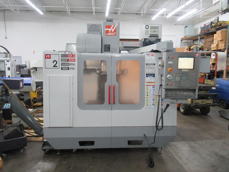
Investing in face milling means buying into a broader technological ecosystem. The foundation is the machine tool itself. Vertical Machining Centers (VMCs) handle standard plates, while Horizontal Machining Centers (HMCs) offer excellent chip evacuation for heavy-duty, uninterrupted production runs.
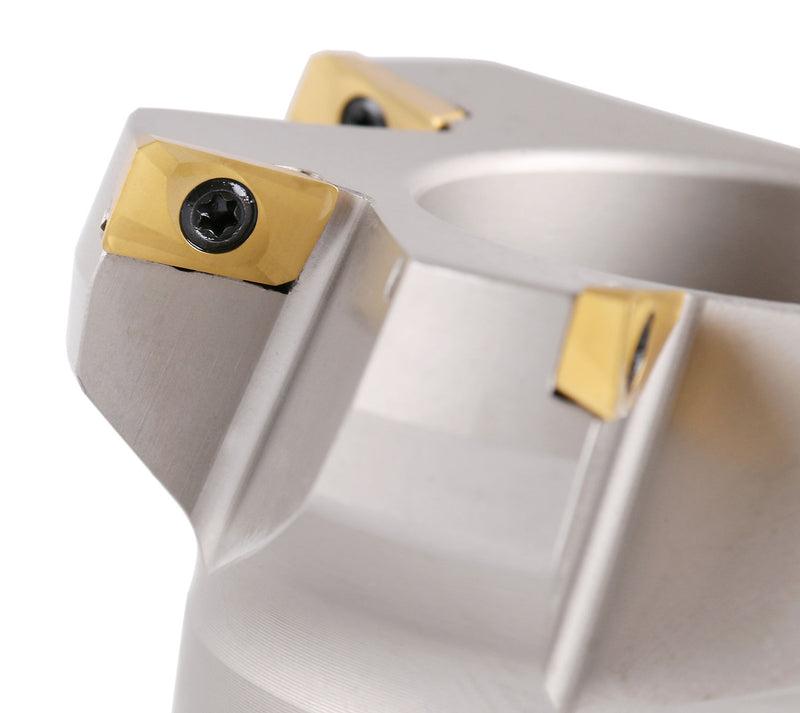
Tooling style dictates performance. A 45-degree cutter is the industry standard, directing cutting forces axially to protect the spindle and allow higher feed rates. Meanwhile, 90-degree cutters are essential when machining true square shoulders alongside flat faces.
Software drives efficiency. Modern CAM systems calculate optimized roll-in trajectories to prevent insert chipping. Additionally, manufacturing ecosystems increasingly integrate digital monitoring, similar to the precision needed for a mould temperature controller, to track spindle load and tool wear.
Quality assurance loops complete the ecosystem. In-machine probing confirms dimensions before the part leaves the fixture. This connected approach ensures stability across the factory floor, a concept familiar to anyone reading a hot runner controller complete guide.
Key Trends Shaping Face Milling in 2026 and Beyond
High-feed milling strategies are dominating the landscape. By utilizing specialized cutter geometries that thin the chip, operators can push feed rates exponentially higher. This trend drastically reduces cycle times without overloading the machine spindle or compromising stability.
Advanced insert coatings are expanding capabilities. Manufacturers are deploying multi-layer PVD and CVD coatings that withstand extreme heat. These innovations allow dry machining of difficult alloys, reducing coolant costs and minimizing thermal shock to the carbide inserts.
Toolpath optimization algorithms have become standard. CAM software now automatically maintains constant engagement angles, ensuring smooth transitions and eliminating sudden spikes in cutting force. This intelligent programming significantly extends tool life and improves the final surface quality.
Automation and pallet pools are transforming spindle utilization. Instead of idle machines waiting for manual setup, automated systems load pre-fixtured raw stock directly into the milling center, enabling lights-out manufacturing and maximizing return on capital investment.
| Key Trend | What It Changes For Buyers |
| High-Feed Strategies | Prioritizes feed rates over depth of cut, requiring specific tool investments. |
| Advanced Coatings | Enables dry machining, reducing coolant dependency and associated costs. |
| Smart Toolpaths | Requires modern CAM software but drastically lowers tooling replacement budgets. |
| Pallet Automation | Shifts buying focus from standalone machines to integrated manufacturing cells. |
Frequently Asked Questions
How do I choose the right cutter diameter?
Select a cutter diameter roughly 1.2 to 1.5 times the width of the workpiece. This optimal ratio ensures the cutter remains constantly engaged, preventing damaging vibrations while allowing efficient chip evacuation during the pass.
When should I use a 45-degree vs. a 90-degree face mill?
Use a 45-degree cutter for general flat surfacing, as it directs forces axially to protect the spindle and allows higher feeds. Choose a 90-degree cutter only when you must mill a true perpendicular shoulder on the part.
What is a wiper insert and when is it needed?
A wiper insert features a slight flat edge that smooths out the feed marks left by standard inserts. It is used when an exceptionally smooth surface finish is required without reducing the feed rate.
How can I troubleshoot chatter during face milling?
Chatter often stems from a lack of rigidity. To fix it, ensure the workpiece is clamped securely, reduce the spindle speed, increase the feed per tooth, or switch to a cutter with differential pitch spacing to break harmonics.
Should I use coolant or machine dry?
For steel and cast iron with modern coated carbide inserts, dry machining is preferred to prevent thermal cracking of the inserts. Use coolant primarily for aluminum, titanium, or heat-resistant superalloys to prevent material from welding to the cutter.
How do I balance surface finish with throughput?
To balance both, utilize high feed rates for roughing passes to remove bulk material quickly, then follow up with a light finishing pass using a wiper insert. This approach maximizes overall throughput while delivering precise final surfaces.
What are the considerations for thin-wall face milling?
Thin walls are prone to vibration and deflection. Use sharp inserts with positive rake angles to minimize cutting pressure. Employ a 90-degree cutter to direct forces radially rather than pushing down into the fragile structure.
How should I handle intermittent cuts over holes?
Intermittent cuts cause severe shock loading on inserts. Reduce the feed rate slightly and use a tougher carbide grade. Programming a roll-in technique rather than a straight entry also helps mitigate the harsh impact forces.
What information must I send a supplier for a tooling quote?
Always provide the workpiece material, required surface finish, available machine horsepower, spindle taper type, and maximum part dimensions. Detailed information ensures the supplier recommends the correct cutter body and insert geometries for your specific setup.
Where can I find more troubleshooting resources?
Beyond machining strategies, maintaining your broader equipment is vital. For related industrial equipment inquiries and detailed technical support, you can review our comprehensive FAQ section to keep your entire production environment running smoothly.