
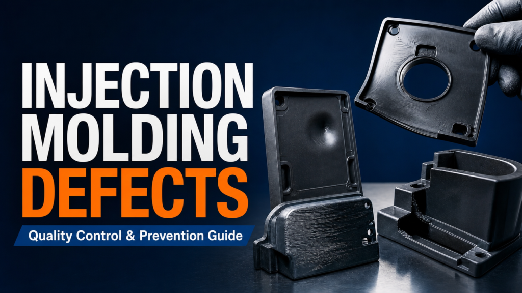
Why Injection Molding Defects Happen
Injection molding defects show up in nearly every shop — even well-run ones. Short shots, warpage, sink marks, flash. Each one costs time, material, and sometimes a whole production run. Understanding why these injection molding defects happen is the first step to stopping them, and knowing the causes and solutions for each is the second.
Most injection molding defects trace back to one of four root causes: machine settings, mold design, material condition, or operator practice. Temperature, pressure, cooling time, gate placement, material moisture — change any of these and the defect picture changes. That makes troubleshooting part detective work, part engineering.
The good news? Almost every common defect has a known fix. This guide walks through the nine most frequent injection molding defects, what causes each one, and the practical steps to correct them on the shop floor. Whether you are fighting a chronic short shot or chasing intermittent flash, the systematic approach in this guide applies to every defect in injection molding you will meet.
9 Common Injection Molding Defects and How to Fix Them
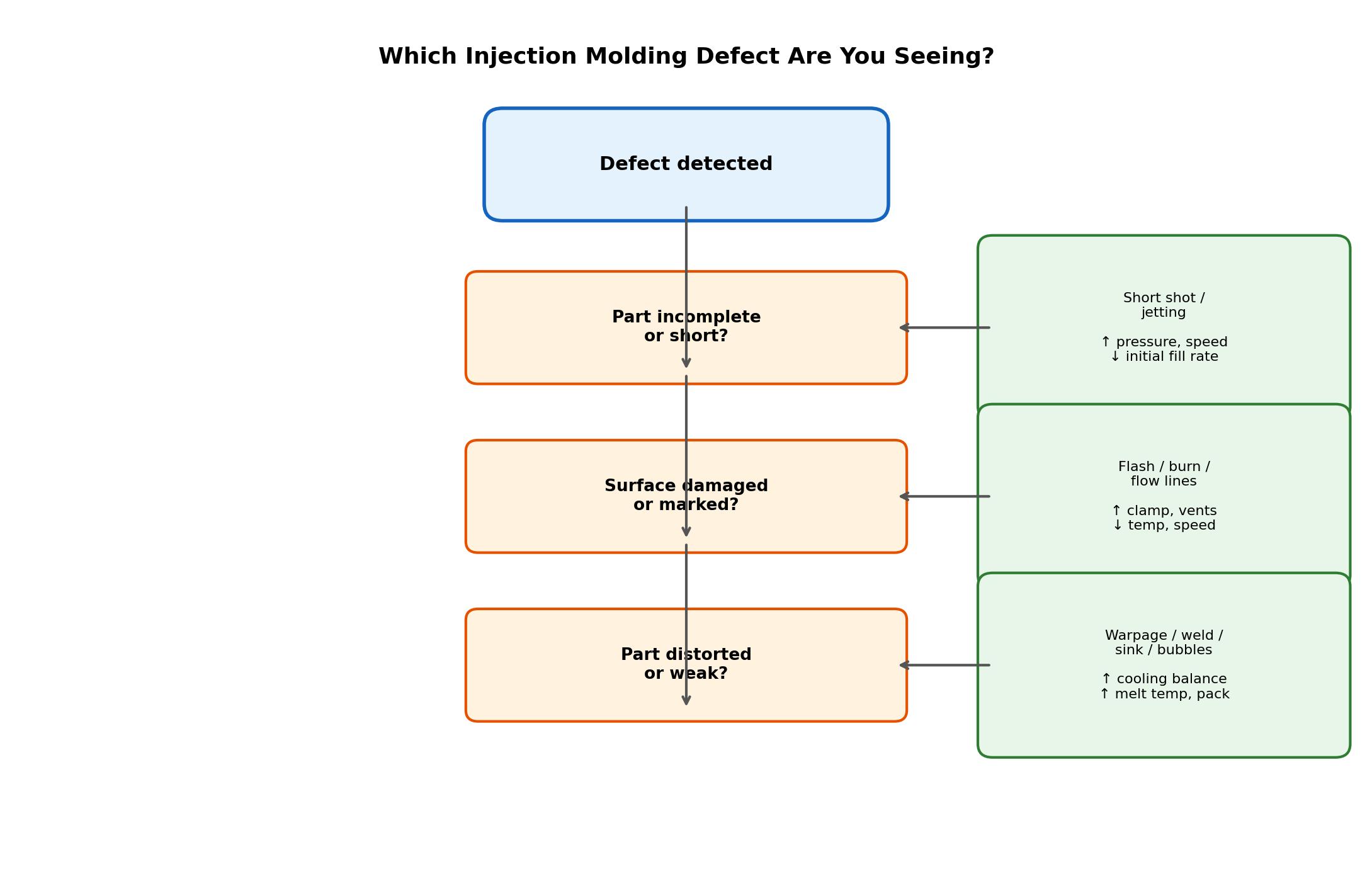
1. Short Shot — Part Not Fully Filled
A short shot means the mold cavity never fills completely. The part comes out with missing sections, usually at the far end of the flow path. It is one of the most visible and most common injection molding defects.
Causes: insufficient injection pressure or speed, low melt temperature, restricted gate or runner, trapped air in the cavity, or a machine shot size set too small for the part volume.
Fixes: raise injection pressure and speed in stages, increase melt and mold temperature, open up the gate or runner cross-section, and add or reposition vents so air can escape. Check that the shot weight is at least 1.5-2x the part weight. This injection molding defect responds fastest to pressure changes, so start there.
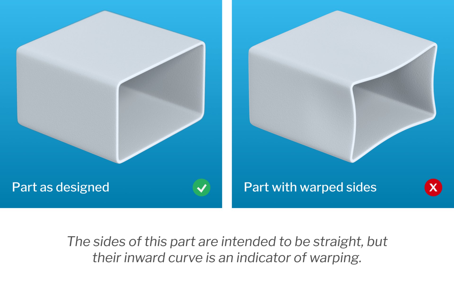
2. Warpage — Part Distorts After Cooling
Warpage is uneven shrinkage that twists or bows the part after ejection. The part looks fine coming out, then bends as it cools to room temperature. It is one of the harder injection molding defects to fix because the root cause is often in the mold design itself.
Causes: non-uniform wall thickness, uneven cooling across the mold, too-high mold temperature, anisotropic shrinkage in glass-filled materials, and improper ejection.
Fixes: design for uniform wall thickness where possible, balance cooling channels so both halves cool evenly, lower mold temperature on the side that cools slower, and extend cooling time before ejection. For filled materials, keep flow direction consistent with the design intent.
3. Sink Marks — Surface Depressions
Sink marks are shallow depressions on the part surface, usually opposite thick sections like ribs or bosses. They happen when the outer skin cools and hardens while the inner core is still shrinking.
Causes: wall sections too thick relative to adjacent areas, insufficient packing pressure or packing time, gate freezing off too early, and low melt temperature that prevents effective packing.
Fixes: increase pack pressure and pack time so the core stays fed as it shrinks, thicken the gate so it stays open longer during packing, reduce rib thickness to 50-60% of the wall, and add cooling time before the gate freezes. Cosmetic parts with visible surfaces are where this injection molding defect causes the most scrap.
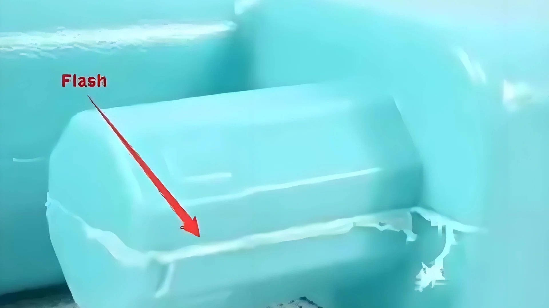
4. Flash — Material Leaking at the Parting Line
Flash is a thin layer of material that escapes the cavity at the parting line, ejector pins, or other gaps. It requires secondary trimming and can damage the mold over time.
Causes: clamp tonnage too low for the projected area, worn or damaged mold surfaces, excessive injection pressure, or too-high melt temperature that reduces viscosity.
Fixes: increase clamp tonnage to hold the mold closed, inspect and re-cut worn parting lines, reduce injection pressure to the minimum needed, and lower melt temperature if viscosity is the issue. Check for obstructions keeping the mold from closing fully. Flash often appears suddenly — a sudden onset usually means mold damage, not process drift.
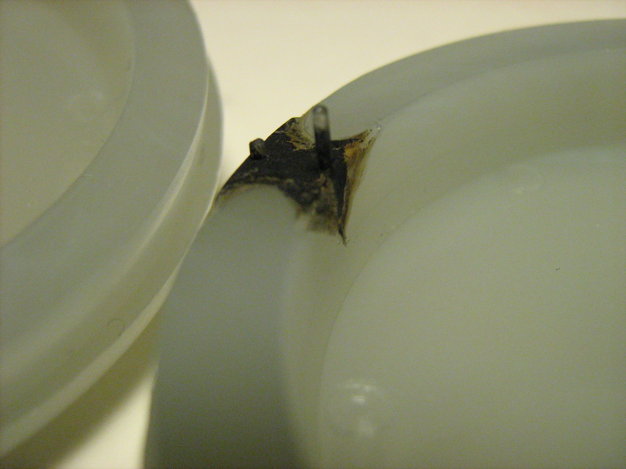
5. Burn Marks — Discolored Spots on the Part
Burn marks appear as dark or brownish streaks, usually at the end of the flow path. They are caused by trapped air that compresses and overheats, degrading the polymer. Unlike some other injection molding defects, burn marks are always localized to the venting and fill-end areas.
Causes: air trapped in the cavity with no escape route, injection speed too fast for the venting capacity, and vents too shallow or blocked.
Fixes: slow the injection speed near the end of fill, deepen or add vents (start with 0.02-0.03mm and increase as material allows), and relocate gates so air pushes toward vented areas. Verify the mold actually has vents — they are often missing in quick repairs.
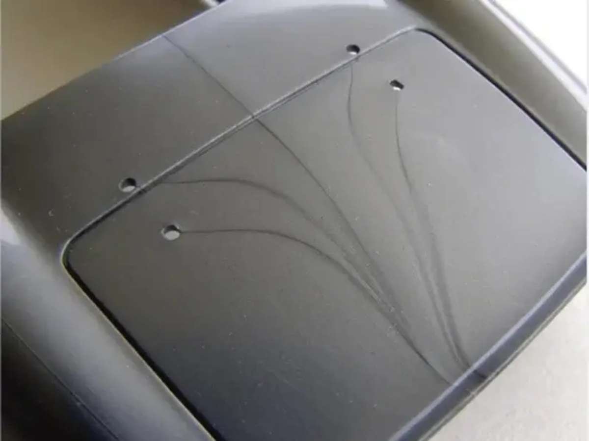
6. Weld Lines — Weak Lines Where Flow Fronts Meet
Weld lines (knit lines) form where two melt flow fronts meet inside the cavity. They are visually distinct and structurally weaker than the surrounding material. For structural parts, this injection molding defect can cause failures at surprisingly low loads.
Causes: flow fronts meeting around cores or inserts, multiple gates, low melt temperature that lets fronts cool before meeting, and insufficient pressure to force the fronts together.
Fixes: raise melt and mold temperature to keep fronts hot, increase injection speed so fronts meet while molten, reposition gates to push weld lines into low-stress areas, and add overflow wells at the weld line location. For structural parts, consider valve gate sequencing to control where fronts meet.
7. Flow Lines — Surface Streaks or Rings
Flow lines are streaks, rings, or wave patterns on the part surface, typically near the gate. They indicate that material cooled in ripples as it filled. Cosmetic housings and visible panels are where this injection molding defect gets rejected most often.
Causes: low melt or mold temperature, slow injection speed during filling, and material flow patterns around the gate.
Fixes: increase injection speed so the melt moves faster than it can ripple, raise melt temperature for smoother flow, and increase mold temperature on cosmetic surfaces. Avoid slow-to-fast injection profiles that create hesitation marks.
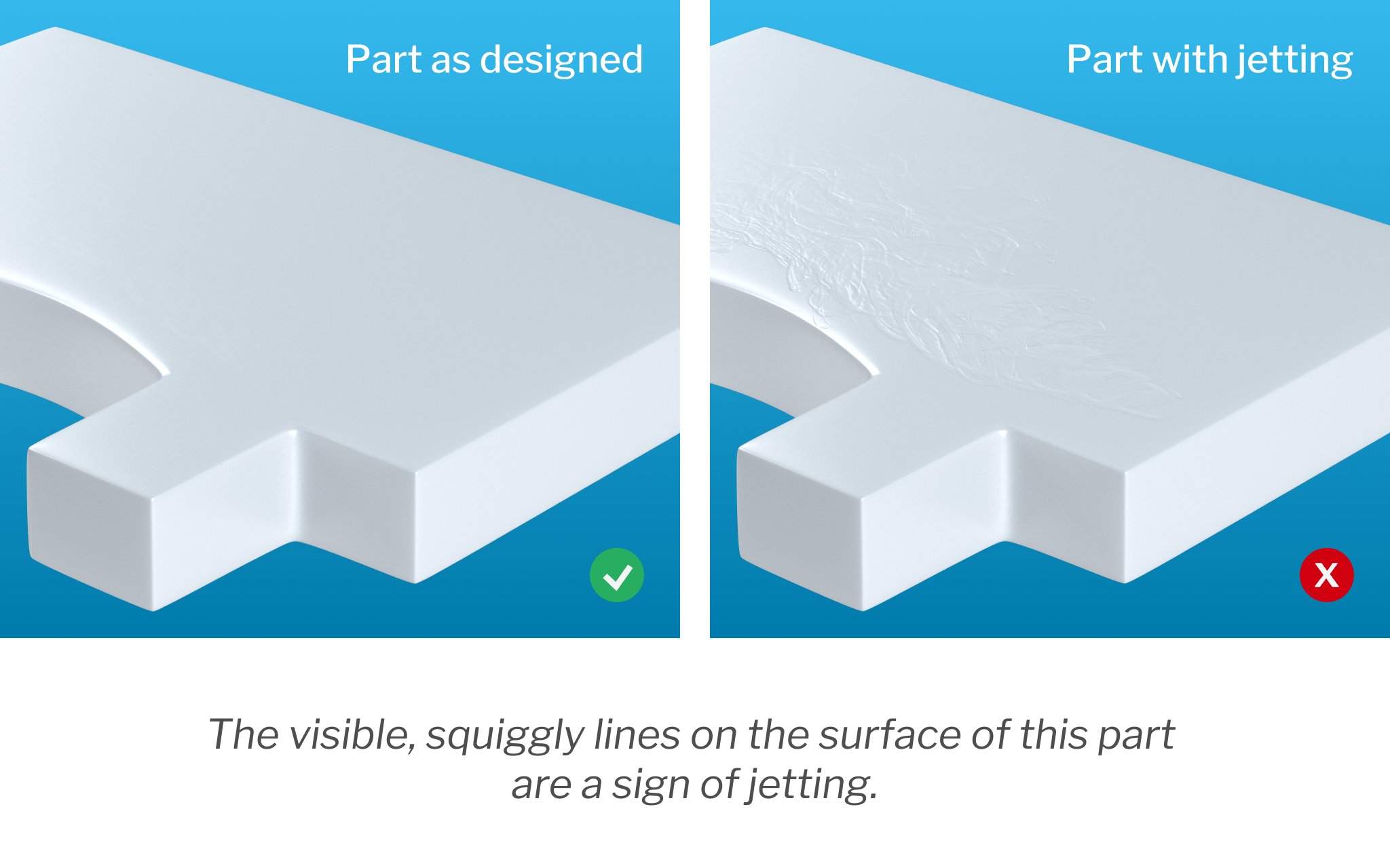
8. Jetting — Snake-like Streaks at the Gate
Jetting happens when melt shoots through the gate into open space instead of flowing along the cavity wall. The result is a snake-like or folded streak at the gate area.
Causes: injection speed too high at the start of fill, gate located opposite an open cavity section, and low melt temperature increasing viscosity.
Fixes: slow the initial injection speed so melt advances along the wall, reposition the gate to aim at a wall or rib, and raise melt temperature. For existing molds, a slower first-stage profile is the fastest fix for this injection molding defect, and it is one of the easier injection molding defects to eliminate once the fill profile is corrected.
9. Bubbles and Voids — Air Pockets Inside the Part
Bubbles appear as gas pockets in the part, often near thick sections. Voids are vacuum pockets that form as thick walls shrink. Both create weak, inconsistent parts and are among the trickier injection molding defects to trace because they are internal.
Causes: trapped gas from material decomposition, moisture in the resin, and thick walls that shrink faster than the material can compensate.
Fixes: dry the material to manufacturer specifications (moisture is a common culprit), reduce melt temperature if gas is from decomposition, increase pack pressure and time, and redesign thick sections where possible.
How Material Choice Affects Injection Molding Defects
Material selection determines which injection molding defects you are most likely to fight. Every resin family has its own sensitivity profile.
Amorphous materials (ABS, PC, PS) shrink uniformly and resist warpage, but show flow lines, weld lines, and surface defects easily. They need higher mold temperatures and carefully tuned injection profiles for cosmetic parts. Most cosmetic-related defects in injection molding trace back to these materials.
Semi-crystalline materials (PP, PA, POM) shrink more and shrink anisotropically, making warpage and sink marks the dominant risks. They tolerate higher mold temperatures and benefit from longer pack phases.
Glass-filled grades shrink less overall but shrink unevenly along the flow direction. Warpage and internal stress are the common problems, and gate placement matters more than with unfilled grades.
High-temperature engineering materials (PEEK, PPS, LCP) demand precise temperature control at every stage. Off-spec temperatures produce brittle parts and surface degradation that look like burn marks but are actually thermal damage.
| Material Family | Common Defects | Key Control Parameter |
|---|---|---|
| Amorphous (ABS, PC, PS) | Flow lines, weld lines, surface defects | Mold temperature, fill rate |
| Semi-crystalline (PP, PA, POM) | Warpage, sink marks, shrinkage | Pack phase, cooling balance |
| Glass-filled grades | Warpage, internal stress | Gate placement, flow direction |
| High-temperature (PEEK, PPS, LCP) | Brittleness, thermal damage | Melt temperature accuracy |
| Elastomers (TPE, TPU) | Flash, air traps, bubbles | Clamp force, venting |
Injection Molding Defects Quick Reference Table
| Defect | Primary Causes | Fastest Fix | Prevention |
|---|---|---|---|
| Short Shot | Low pressure/speed, trapped air | Increase injection pressure | Proper venting, adequate shot size |
| Warpage | Uneven cooling, thick sections | Balance mold temperature | Uniform wall design |
| Sink Marks | Thick walls, early gate freeze | Increase pack time | Rib thickness ≤ 60% of wall |
| Flash | Low clamp, worn mold | Increase clamp tonnage | Maintain parting line |
| Burn Marks | Trapped air, fast injection | Add/deepen vents | Vent design at fill end |
| Weld Lines | Cool flow fronts | Raise melt temperature | Gate placement, overflow wells |
| Flow Lines | Slow fill, low temperature | Increase injection speed | Consistent fill rate |
| Jetting | Fast initial injection | Slow first-stage speed | Gate aimed at wall |
| Bubbles/Voids | Moisture, thick walls | Dry the material | Proper drying, pack pressure |
How to Troubleshoot Injection Molding Defects Systematically
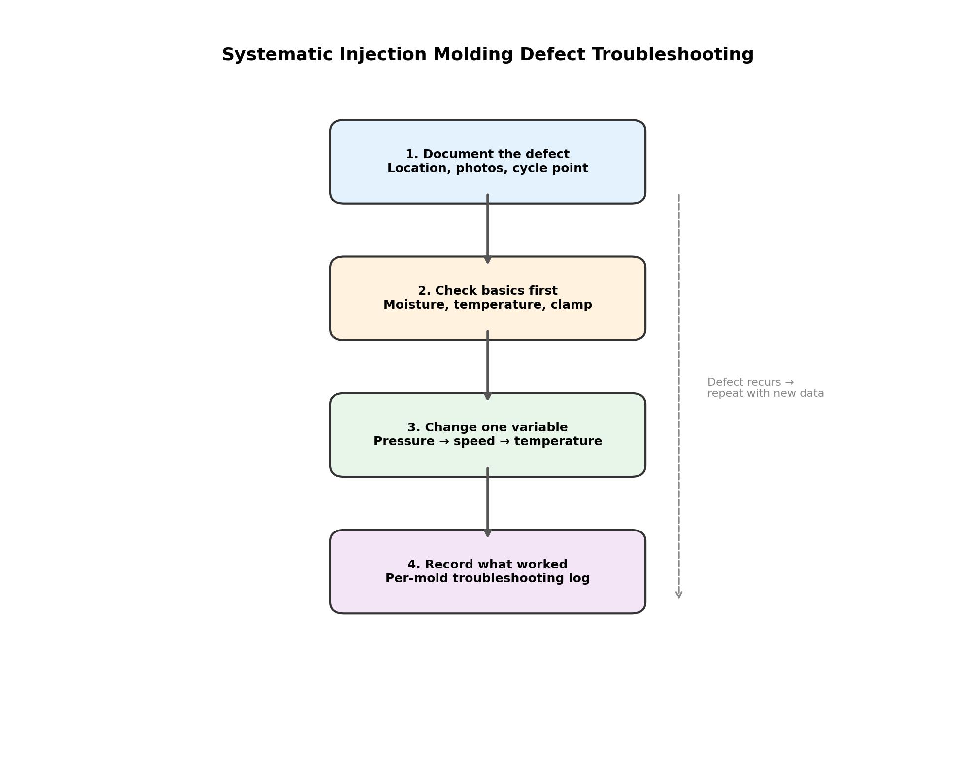
Randomly changing settings usually makes things worse. A structured approach isolates the root cause faster and documents what actually worked.
Step 1 — Document the defect. Location, appearance, when it appears in the cycle, and whether it changes across the shot sequence. Take photos. A short shot at the far end of the cavity points to pressure or venting; a short shot near the gate points to machine shot size.
Step 2 — Check the basics first. Material moisture, temperature readings, and clamp tonnage account for a surprising share of injection molding defects. Verify the material was dried per spec and that all thermocouple readings match the setpoints before touching anything else. Over half of the injection molding defects reported on the floor trace to moisture or temperature drift.
Step 3 — Change one variable at a time. Adjust injection pressure, then speed, then temperature — one per trial. Run three to five parts after each change and compare. Changing multiple variables at once makes it impossible to know which fix worked.
Step 4 — Record what worked. Keep a per-mold troubleshooting log. The next time the same defect appears, the fix is already documented. This turns reactive problem-solving into institutional knowledge that reduces defect rates over time.
Defect Reduction Through Better Temperature Control
Temperature is the common thread running through most injection molding defects. Warpage follows uneven cooling. Burn marks follow overheating. Weld lines follow premature cooling. Getting temperature right across the entire process eliminates a surprising number of defects at once.
Mold temperature is controlled by the mould temperature controller circulating water or oil through the mold. Stable mold temperature produces consistent shrinkage, fewer sink marks, and less warpage. For hot runner systems, each nozzle zone needs independent control — a multi-zone hot runner controller keeps melt temperature uniform from nozzle to nozzle, reducing short shots and flow variations across cavities.
Temperature-related defects like stringing are covered in depth in our guide to stringing and short shots in injection molding. Both defects are temperature-sensitive and respond quickly to better control.
Defect Inspection and Quality Control
Catching defects early beats fixing them after a full run. Practical inspection approaches range from manual checks to automated systems.
First-article inspection. The first parts from a new mold setup should be measured and compared against the approved sample. Dimensional checks, surface inspection, and functional tests catch issues before full production starts. Many shops hold first articles for 30-60 minutes of production before releasing the mold.
Statistical process control. Track defect rates per defect type and per mold. A pareto chart showing which injection molding defects occur most often points the improvement effort at the highest-impact problem first. Typical defect rates in a stable process run under 2-3%; higher rates signal a process or material issue.
Automated vision inspection. In-line cameras can flag burn marks, short shots, flash, and surface defects at cycle speed. For high-volume packaging and medical parts, automated inspection is often mandatory for quality certifications.
Frequently Asked Questions
What are the most common injection molding defects?
Short shots, warpage, sink marks, flash, burn marks, weld lines, flow lines, jetting, and bubbles/voids are the nine most frequent injection molding defects. Flash and sink marks are often cited as the most common injection molding defects in general-purpose molding, while weld lines and warpage dominate in structural and cosmetic parts. The full list of defects in injection molding extends further, but these nine cover most shop-floor rejects.
How do I fix short shots in injection molding?
Increase injection pressure and speed in steps, raise melt and mold temperature, and verify the shot size covers the part volume. Also check venting — trapped air prevents the cavity from filling completely. If the defect appears only at the far end of the flow, venting or pressure is the likely culprit.
What causes warpage in injection molding?
Uneven cooling and non-uniform wall thickness are the main causes. The part shrinks at different rates in different areas, causing it to twist or bow. Balance the cooling channels, design for uniform walls, and extend cooling time before ejection to reduce warpage.
Why do sink marks appear on my parts?
Sink marks come from thick sections shrinking after the surface skin has hardened. Increase pack pressure and pack time so the core stays fed, keep the gate open longer, and reduce rib or boss thickness relative to the wall.
How do I prevent flash in injection molding?
Raise clamp tonnage to keep the mold closed against injection pressure, inspect and maintain the parting line, and reduce injection pressure to the minimum that fills the part. Flash that appears suddenly usually signals a worn or damaged mold surface. Of all the common injection molding defects, flash is the one most often caused by mechanical wear rather than process settings.
Are weld lines always weak?
Weld lines are generally the weakest point in the part, but the severity depends on how well the flow fronts fused. Higher melt temperature and pressure create stronger weld lines. If a weld line is unavoidable, position it in a low-stress area through gate placement.
Can better temperature control really reduce defects?
Yes — temperature drives shrinkage, flow, and cooling behavior. Stable mold temperature via a reliable temperature control unit reduces warpage, sink marks, and dimensional variation. Consistent melt temperature in hot runner systems reduces short shots and flow defects across cavities. In practice, fixing temperature control is the single highest-leverage move against the most common injection molding defects. For a step-by-step selection process, see our guide on how to choose temperature controllers.
How much does a defective part cost?
Beyond the material itself, a defective part costs machine time, labor, and potentially a production halt. At 20-second cycle times, even a 5% defect rate wastes 36 minutes of machine time per 8-hour shift. Reducing defect rates from 5% to 2% on a three-shift operation saves hundreds of machine hours a year.
Conclusion
Injection molding defects are frustrating, but they are also diagnosable and fixable. The nine injection molding defects covered here — short shots, warpage, sink marks, flash, burn marks, weld lines, flow lines, jetting, and bubbles — account for the majority of rejects in most molding operations. Each defect in injection molding has known causes and proven fixes, and the injection mold defects we covered map directly to process and design variables you can control.
The common denominator across most injection molding defects is process control, especially temperature. Stable mold temperature and consistent melt temperature eliminate whole families of defects at once. That is why temperature control equipment deserves attention on every shop floor — and why the solutions for injection molding defects so often start in the temperature cabinet, not the molding machine.
At C N Topower, we build temperature control solutions for injection molding — from mould temperature controllers to multi-zone hot runner controllers. If temperature-related defects are eating into your yield, contact our team for a control solution matched to your process.