
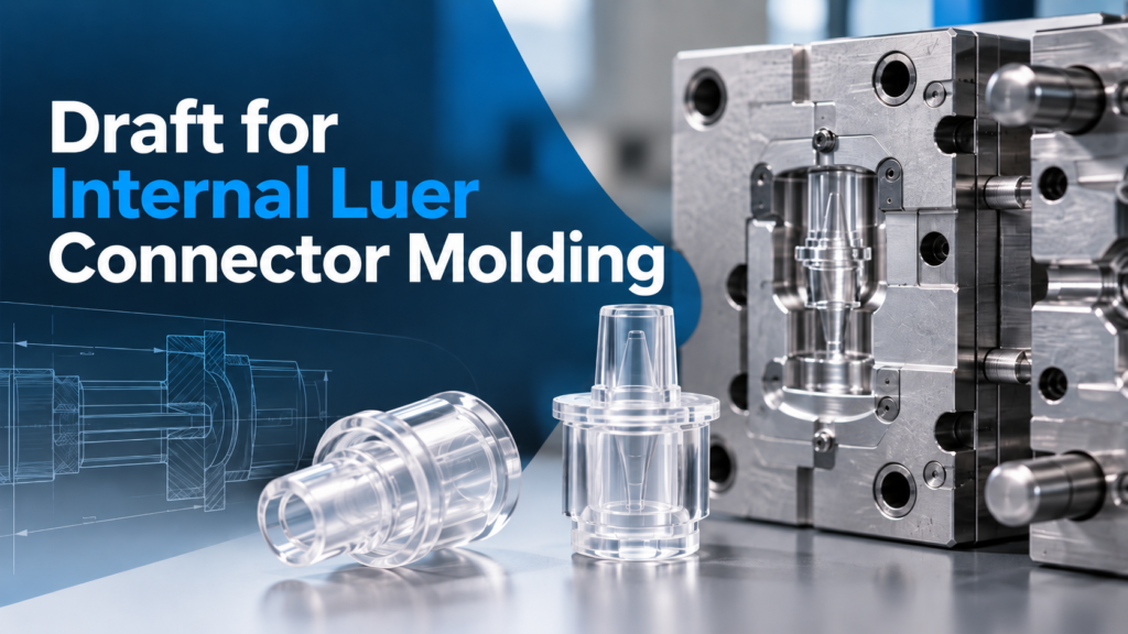
Why Draft for Internal Luer Connector Molding Breaks Normal Rules
Draft for internal luer connector molding almost never follows the shop-floor default of "one to two degrees per side." A luer part is small, thin-walled, and molded in the millions on a tight cycle. The surface that decides whether the part ejects cleanly sits inside a bore 2 to 6 mm across, formed by a core pin you cannot see once the tool closes. Get the taper wrong by half a degree and you scrap a whole shift.
Most design guides treat draft as a single number pulled from a table. Draft for internal luer connector molding resists that shortcut, because the surface doing the work is hidden and the tolerances are tight.
Consider what happens on a 32-cavity medical tool of the kind our medical injection mold tooling is built around. Each cavity holds a slender core pin forming an internal fluid path. Ejection force, melt pressure, and shrinkage all push against that pin at the same moment. Without taper on that internal surface, the plastic grips the steel and the pin stretches before the part releases. Sometimes the part tears. Sometimes the pin bends, and now every cavity downstream of it drifts out of tolerance.
So draft here is not decoration. Draft for internal luer connector molding is the mechanism that converts a mechanical lock into a sliding fit. The rest of this piece walks through the numbers, the standard, and the failure modes that decide whether draft for internal luer connector molding works. Readers building a threaded feature on a draft angle on a screw-off slide will recognize the same physics in a different package.
The commercial backdrop matters too. Grand View Research valued the global medical injection molding market at USD 25.1 billion in 2025 and projects USD 26.5 billion for 2026, while Research and Markets reports growth from USD 27.32 billion in 2025 to USD 29.42 billion in 2026 at a 7.7% compound annual rate. Two research houses, two methodologies, one direction. More luer parts, on shorter cycles.
What the 6% Luer Taper Already Gives You
A luer connector is defined by its taper, not its draft. The current reference is ISO 80369-7, which replaced the older ISO 594-1 and ISO 594-2 documents for intravascular and hypodermic connectors. That standard fixes the small-bore connector at a 6% taper, meaning the diameter changes 6 units over 100 units of axial length.
Run the trigonometry and the numbers matter. A 6% slope gives roughly 1.72 degrees per side, or about 3.43 degrees included. Compare that against the usual minimum draft for a polished steel core: 1 degree per side on surfaces finished between Ra 0.8 and 1.6 micrometres, and 1.5 to 2 degrees for most industrial parts. The official ISO 80369-7:2021 standard page carries the dimensional tables that define the cone.
That is the trap. The sealing surface passes the draft check on its own, so engineers tick the box and move on. Then the part sticks anyway, because the failure happens somewhere the taper does not reach. Any discussion of draft for internal luer connector molding has to start past the cone, not at it. The working number comes from the worst internal surface, never from the sealing face.
Worth stating plainly: the standard tells you what the finished connector must measure. It says nothing about how you cut the steel that makes it. Draft stays a molding decision, and it belongs to the molder rather than the standards committee.
Where the Taper Stops Helping
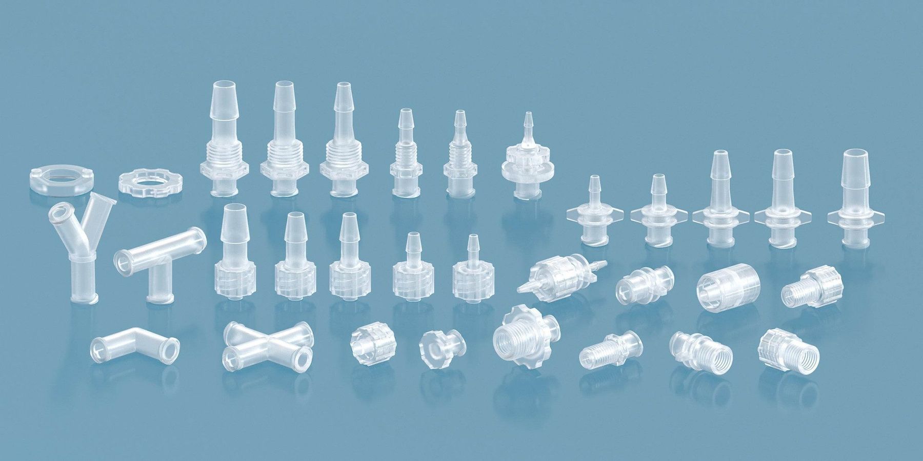
Look at a female luer lock in cross section. The 6% bore occupies maybe a third of the internal length. Everything behind it is fair game for trouble: the straight section that feeds the bore, the locking thread, the hex or wing flats on the outside, and any blind pocket used for a filter or a check valve.
Straight sections are the usual culprit. A designer sizes an internal channel to match tubing, so it runs parallel to the pin for its whole length. That single choice undoes careful draft for internal luer connector molding everywhere else on the part, and no amount of taper on the cone compensates for it.
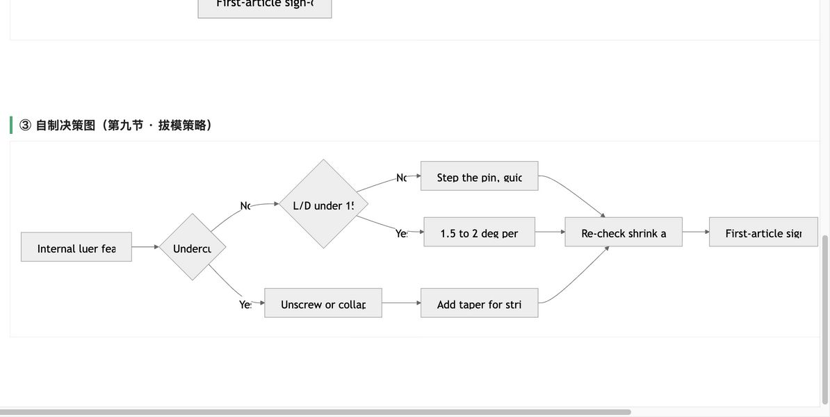
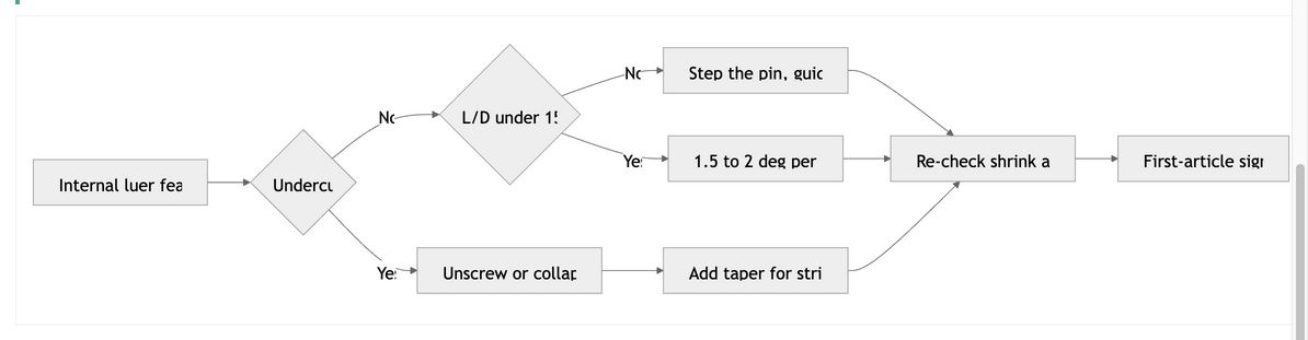
Locking threads deserve separate treatment. A luer lock thread is an undercut, so it cannot release on a straight pull. Either the core unscrews, or the plastic strips over the thread form, or you split the tool with a collapsible core. Each route carries its own draft requirement, and stripping a thread demands far more taper than a plain bore.
Then there is depth. Core-pin deflection scales with the cube of unsupported length against diameter, a relationship that punishes optimism in draft for internal luer connector molding. Push a 3 mm pin 30 mm deep and the tip wanders under injection pressure even before you argue about degrees.
Textured surfaces make the arithmetic worse. A frosted medical grip adds roughly 0.5 to 1 degree of draft per 0.025 mm of texture depth, so a 0.075 mm bead blasted finish quietly demands about 3 extra degrees on that face. Meanwhile the common molding defects that follow bad internal draft, drag marks, short shots, and stress whitening, show up on the part long after the mold is built.
Three Numbers That Govern Draft for Internal Luer Connector Molding
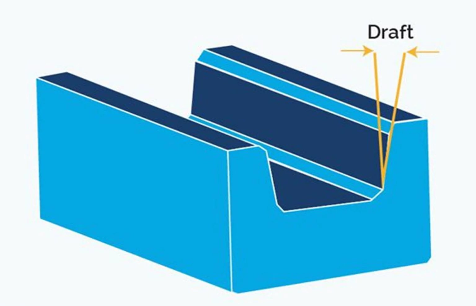
Three figures carry almost all the risk on an internal luer feature: draft per side, feature depth, and the ratio between them. Every draft for internal luer connector molding decision traces back to one of the three.
Draft per side comes from a chart, then gets adjusted for surface finish, resin, and how much shrink the material develops. Depth comes off the part drawing. The ratio is where designers get caught, because the same 1.5 degrees behaves very differently at 8 mm and at 40 mm.
A practical reference for internal luer geometry follows. Treat it as a starting point for a DFM conversation, not a substitute for one.
| Parameter | Unit | Typical value for internal luer features | Why it matters |
|---|---|---|---|
| Draft, polished core | degree per side | 1.0 (minimum), 1.72 dictated by the 6% taper | Below 1 degree the pin drags steel against plastic and ejection force climbs |
| Draft, textured core | degree per side | Add 0.5 to 1 per 0.025 mm of texture depth | Texture removes the smooth sliding surface the baseline draft assumed |
| Feature depth | mm | 8 to 40 on full luer lock bodies | Sets unsupported core-pin length and the bending load case |
| Core pin length to diameter | ratio | Keep under 10:1, flag anything past 15:1 | Deflection grows with the cube of length, not linearly |
| Wall thickness | mm | 0.8 to 1.5 on medical luer bodies | Thin walls cool fast and shrink onto the core before ejection starts |
| Mold temperature | °C | 60 to 90 for polycarbonate, lower for polypropylene | Cooler steel shrinks more, which tightens the grip on the pin |
| Ejection force budget | % of machine capacity | Under 70 | Headroom disappears the moment draft is marginal |
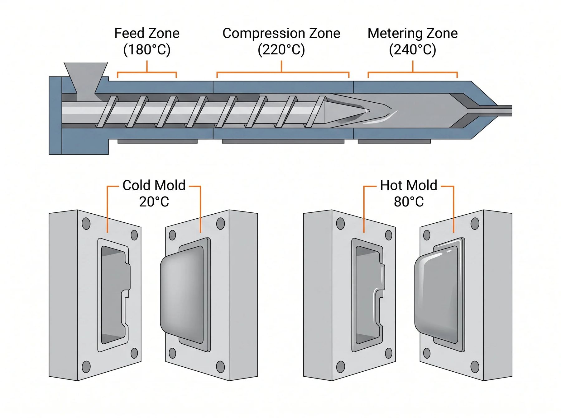
The mold temperature line surprises people. Running a luer tool cool shortens the cycle, but the part contracts further onto the core before the press opens. A tool that ejects cleanly at 90 °C can bind at 60 °C with identical steel geometry. Draft for internal luer connector molding therefore cannot be signed off without the process window attached.
Tooling around the cavity plays a role too. Even thermal control across a multi-cavity block, held by a stable hot runner temperature controller, keeps shrink consistent from cavity to cavity. Uneven shrink means one cavity needs 2 degrees where its neighbour survives on 1.2.
Reading ISO 80369-7 Without a Standards Subscription
Engineers without a copy of the standard still need to design to it. The practical path runs through the dimensional tables published in supplier catalogues and the gauge drawings that testing labs use.
What the document fixes: the taper, the specified dimensions at both ends of the cone, the gauging method, and the misconnection resistance that separates the various parts of the ISO 80369 family. Reference connectors and go/no-go gauges exist so a supplier can prove a part conforms without owning the text.
What it leaves open: gate location, cooling layout, ejection strategy, and every draft angle on the core side. Those belong to the mold builder, and they are where draft for internal luer connector molding is actually decided.
Medical buyers ask for conformity evidence rather than a design recipe, so the molder carries the burden of translating a gauge dimension into steel geometry. Get that translation wrong and a conforming part still sticks.
Material Behavior in Medical Luer Molding
Resin choice shifts the requirement through two channels: how much the part shrinks, and how stiff it stays while hot. Both channels move draft for internal luer connector molding in the same direction, so material and angle get specified together or not at all.
Polycarbonate is the classic luer material. It holds dimensions after sterilization, machines into clear parts, and shrinks around 0.5 to 0.7 percent. Rigid grades resist the slight compression of a taper joint without cracking.
Polypropylene appears in single-use luer bodies where cost and chemical resistance dominate. It shrinks far more, often 1.5 to 2.5 percent, and that extra contraction wraps the core pin harder. A draft that works in polycarbonate can bind in polypropylene on the same tool, which is why draft for internal luer connector molding has no single universal number.
ABS copolymers sit between the two and take well to gamma sterilization, though they yellow more than polycarbonate over repeated cycles.
Higher-end devices use polysulfone, PEEK, or cyclic olefin copolymer where autoclave cycles or optical clarity matter. These resins run hot and cost more, so thin-wall sections cool unevenly and warp. Warp effectively steals draft on one side of a bore while adding it on the other.
Crystalline and amorphous resins do not shrink alike, and the difference shows up directly in draft for internal luer connector molding. Semicrystalline grades such as polypropylene pack a sharp volume change across the melt transition. Amorphous polycarbonate shrinks gradually and predictably. The practical consequence: semicrystalline parts need more draft, and they need it measured after the part has fully cooled rather than on the bench at five minutes.
Mold surface temperature ties back into this. A mould temperature controller holding the core side steady removes one variable from a process that already has too many.
Five Checks Before You Approve Draft for Internal Luer Connector Molding
One review, run before the steel is cut, catches most internal luer draft problems. It takes an afternoon and saves weeks, which is cheap next to re-cutting a core pin after draft for internal luer connector molding has already been frozen into the tool.
Check one. Isolate every internal surface a core has to pull. Colour the part model by which half forms each face. Anything formed by a core that withdraws along the machine axis belongs on the list, including small radii and the floor of a blind pocket.
Check two. Measure depth against diameter for each core pin. Compute the ratio. Anything past 15:1 needs either more draft, a shorter unsupported length, or a stepped pin with a guided tip.
Check three. Add the texture allowance. Take the finish specification from the drawing and convert it to extra degrees before anyone approves the print.
Check four. Check the shrinkage path. Run the material's actual shrink figures against the tightest internal dimension. Where the tolerance band is smaller than the shrink variation, draft alone will not hold the dimension.
Check five. Simulate ejection, not just filling. Fill analysis shows whether the cavity packs. Ejection analysis shows the force needed to break the grip on a core pin. Only the second one predicts sticking.
Failure Patterns and Their Fixes
Internal luer draft problems repeat themselves across shops, and a handful of causes accounts for most of them. Draft for internal luer connector molding failures are rarely exotic. The table below maps each symptom to what actually causes it, so a fix lands on the cause instead of the symptom.
| Failure pattern | Root cause | Corrective action |
|---|---|---|
| Longitudinal drag marks inside the bore | Draft below 1 degree per side, or a polished finish that was never restored after polishing | Repolish along the draw direction, then verify draft with a taper gauge rather than a print |
| Stress whitening at the bore mouth | Ejection force too high because the thin wall shrank onto the pin | Raise core-side temperature, shorten hold time, add draft before adding ejector force |
| Core pin bends or breaks | Length-to-diameter ratio past 15:1 with no tip guidance | Step the pin, add a guided tip, or split the bore into two shallower features |
| Dimensional drift on the taper diameter | Uneven shrink between cavities or across the shot | Balance cooling, then re-qualify the 6% taper with reference gauges |
| Short shot at the tip of the bore | Pin runs too cool, so melt freezes before the cavity fills | Add core-side heating or revise the bubblers and baffles layout |
| Parts stick only on humid days | Material moisture swinging shrinkage between shifts | Fix drying, not draft. Check the resin dryer before touching the tool |
| Thread stripping on luer lock forms | Stripping a thread that was never designed to flex that far | Move to unscrewing or a collapsible core instead of forcing a straight pull |
One entry deserves emphasis. The humid-day problem gets blamed on draft so often that tools get re-cut for nothing. Moisture in hygroscopic resin changes shrink, and shrink changes grip. Verify the dryer before you schedule the grinder, and treat draft for internal luer connector molding as innocent until the resin is proven dry.
Tooling and Hot Runner Choices for Luer Cavities
Cavity count drives the draft conversation, because draft for internal luer connector molding has to work in the worst cavity rather than the average one. A 4-cavity pilot tool tolerates uneven cooling because the shot is short. Scale to 32 or 64 cavities and the same imbalance makes some cavities stick every cycle while others never do.
Hot runner selection matters more than most medical molders expect. Valve gate systems give independent shutoff per cavity, which lets you tune fill balance without altering gate size. Thermal uniformity across the manifold then holds shrink consistent, and consistent shrink is what lets a single draft angle serve every cavity.
Pair the manifold with a hot runner system sized to the shot rather than the press, and add a modular hot runner temperature controller so a single zone failure does not scrap the tool's output. Small parts with long cores are unforgiving about thermal drift, and drift is the quiet enemy of any draft for internal luer connector molding that looked fine on paper.
Accessories finish the picture. Hot runner controller accessories such as thermocouple upgrades and wiring harnesses keep zone readings honest, and an honest reading is the only way to know whether a sticking part is a draft problem or a temperature problem.
Validating Draft on the First Article
First-article inspection on a luer tool should measure the internal geometry, not just the outside. A pin gauge confirms the bore diameter but says nothing about taper. Taper gauges and reference connectors, the same ones the standard calls for, catch the angle.
Optical comparators work for short bores and moulded samples cut in half, which is usually enough to confirm draft for internal luer connector molding on a sample. Computed tomography handles the awkward cases where you need the internal cone intact. Either method gives a number to compare against the drawing rather than a feeling.
Run the inspection across a process window, not a single setting, since draft for internal luer connector molding only holds while the window holds. Bump mold temperature by 10 °C, re-run, and measure again. The internal diameter will move. If it moves outside the tolerance band, no draft angle will rescue the part; the process window itself is too wide.
Ejection force logging helps here. Many presses report peak ejection pressure per cycle, and a slow upward drift across a production run signals that the draft for internal luer connector molding has no margin left. Catch the drift early and you re-cut a pin. Catch it late and you replace a cavity insert.
Medical customers increasingly ask for this evidence as part of a supplier qualification. Documented first-article data, tied to a quality and capability system, does more for an order than a lower quote.
Frequently Asked Questions
Is 1.5 degrees per side enough for draft for internal luer connector molding?
Usually yes on a short, polished bore in polycarbonate, and no on a long bore in polypropylene. The angle alone does not decide. Depth-to-diameter ratio, resin shrink, and core-side temperature all shift the answer, so treat 1.5 degrees as the middle of a range and check the other three variables.
Why does the 6% luer taper not count as draft on its own?
It does count, on the sealing cone. About 1.72 degrees per side puts the taper right at the accepted minimum. The problem is coverage. A luer body contains straight feed sections, locking threads, and grip flats where the taper provides nothing, so the working figure for draft for internal luer connector molding comes from the worst internal surface rather than the cone.
Can I strip a luer lock thread instead of unscrewing it?
Sometimes, with a compliant resin and a shallow thread form. Stripping needs far more taper than a plain bore because the plastic has to deform over the thread crest. If the thread is deep or the resin is rigid, plan for unscrewing or a collapsible core from the start.
How does sterilization change the draft requirement?
Indirectly. Gamma and autoclave cycles relax molded-in stress and can move dimensions slightly. A part that ejects cleanly before sterilization may grip differently after, so qualify draft for internal luer connector molding on sterilized samples when the connector is a critical fluid path.
What draft do I need on a textured internal surface?
Add roughly 0.5 to 1 degree per side for every 0.025 mm of texture depth on top of the baseline for a polished surface. A 0.075 mm frosted finish therefore needs about 3 extra degrees, which often pushes a design past what the core pin can tolerate.
Do all cavities in a multi-cavity tool need the same draft?
They should, and achieving that is a cooling and hot runner balance problem rather than a steel problem. Draft for internal luer connector molding should be identical across cavities; the process around it is what varies. If one cavity needs extra draft to release, the imbalance will show up as a dimensional spread long before it shows up as sticking.
When should I use a stepped core pin instead of more draft?
Whenever the length-to-diameter ratio passes roughly 15:1. A step shortens the unsupported span and guides the tip, which reduces deflection more effectively than adding a half degree of taper to a pin that is already flexing.
Where This Leaves Your Luer Project
Draft for internal luer connector molding rewards arithmetic over habit. Start from the 6% taper the standard demands, then work outward through every surface a core has to pull. Check depth against diameter. Add the texture and shrink allowances before the print is released. Validate with gauges that measure angle, not just diameter.
Do those things and a 32-cavity medical tool runs a stable cycle with margin to spare. Treat draft for internal luer connector molding as an engineering calculation rather than a line on a drawing. Skip the calculation and the same tool spends its life in the maintenance bay while scrap rates creep up and nobody can explain why.
If your next luer project needs tooling built with that draft for internal luer connector molding arithmetic already done, talk to our engineering team before the design freeze rather than after the first shots.