
Injection Molding Screw Off Slide Draft: 5 Mistakes That Cause Sticking and Scrap
Why do so many threaded injection molded parts come out of the tool with drag marks, stripped thread flanks, or parts that simply refuse to eject? In most cases the fault sits in one geometric parameter: the injection molding screw off slide draft angle. When a mold uses a sliding core to release external threads, the draft on that slide determines whether the part releases cleanly or fights the steel on every cycle.
This guide walks through how draft behaves on a screw-off slide, the exact angles to specify by material, and the five mistakes that turn a good mold design into a rework ticket. Understanding the injection molding screw off slide draft rules is the fastest way to cut scrap on threaded tooling.
What Is a Screw-Off Slide and Why Draft Angle Matters
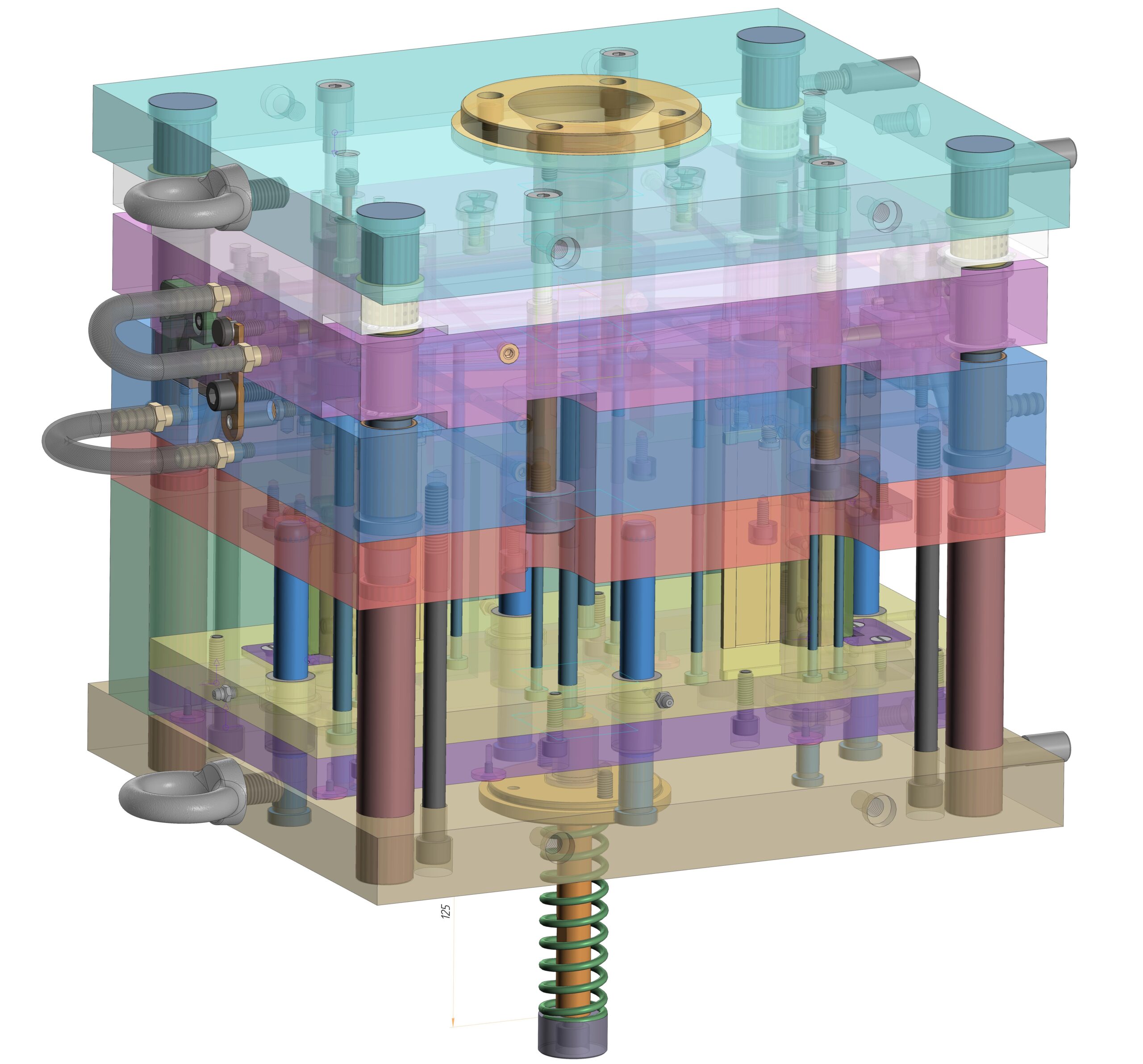
A screw-off slide is a side-action core used in injection molds to form external threads, bayonet lugs, or other features that wrap around the part periphery. Instead of rotating the core like an unscrewing mold, the slide retracts laterally after the mold opens, allowing the threaded portion to lift away without interference. Because the thread flanks interlock with the slide steel, any roughness, insufficient taper, or misaligned parting line creates mechanical binding the moment ejection begins.
Draft angle on a screw-off slide works exactly like draft on any vertical mold wall, but the stakes are higher. Thread peaks and roots present deep, narrow pockets where the plastic grips the tool. Shrinkage pulls the part tight against the slide core, and without enough taper the ejector system has to overcome that grip through force alone. The result is visible damage: scuffed cosmetic surfaces, deformed thread forms, and short ejector pin life.
Standard practice across mold shops puts draft for screw-off slide surfaces between 1 and 3 degrees per side. Materials with high shrinkage or strong adhesion, nylon for example, need more; slippery low-shrinkage resins like polyethylene can run at the lower end. Texture adds another layer, roughly 1 degree for every 0.25 mm of texture depth, because the surface roughness mechanically locks the plastic to the steel. The basic principle behind draft in engineering is documented across manufacturing references, and it applies with extra force wherever threads are involved.
Threaded Parts and the Injection Molding Market
Threaded closures, medical connectors, and automotive fasteners represent one of the fastest-growing corners of the molding industry. The global injection molding market reached roughly USD 335 billion in 2025 and is projected to climb to USD 588.71 billion by 2035, a compound annual growth rate of about 5.8 percent (Precedence Research, 2026). Packaging leads application demand at 28 percent of the market, and caps and closures are the single largest family of threaded molded parts.
That volume puts enormous pressure on mold builders to make threaded tools run reliably from day one. A cap mold with 32 cavities that produces drag marks or sticking parts does not just lose one cycle; it multiplies the defect across every cavity and every shift. Screw-off slide draft design sits directly in that economics, which is why experienced tooling engineers treat the draft table as a gate review item rather than a recommendation. Common injection molding defects like drag and sticking trace back to geometry decisions made long before the press started running.
Three Draft Rules Every Screw-Off Slide Must Follow
Rule one: never leave the thread flanks vertical. A zero-draft thread flank guarantees drag marks on the first shot. Mold designers should add taper to the flank geometry where the thread form allows it, typically on the non-engaging flank, keeping the functional flank profile intact.
Rule two: the core side needs more draft than the cavity side. Plastic shrinks onto the core during cooling, so the internal surfaces generate higher ejection force. A common guideline is 0.5 to 1 degree additional draft on the core side, and this difference becomes critical on deep thread sections or high-shrinkage resins such as glass-filled nylon.
Rule three: draft direction must follow the slide retraction path. The taper should widen toward the opening direction so the part releases progressively, never in a way that creates a secondary undercut inside the slide geometry itself. This sounds obvious, yet draft analysis tools regularly flag inverted taper on slide-mounted thread forms during DFM reviews. Undercut injection molding rules apply here in reverse: the designer adds draft to avoid creating a hidden undercut on the slide face.
Step-by-Step: Designing Draft for a Screw-Off Slide
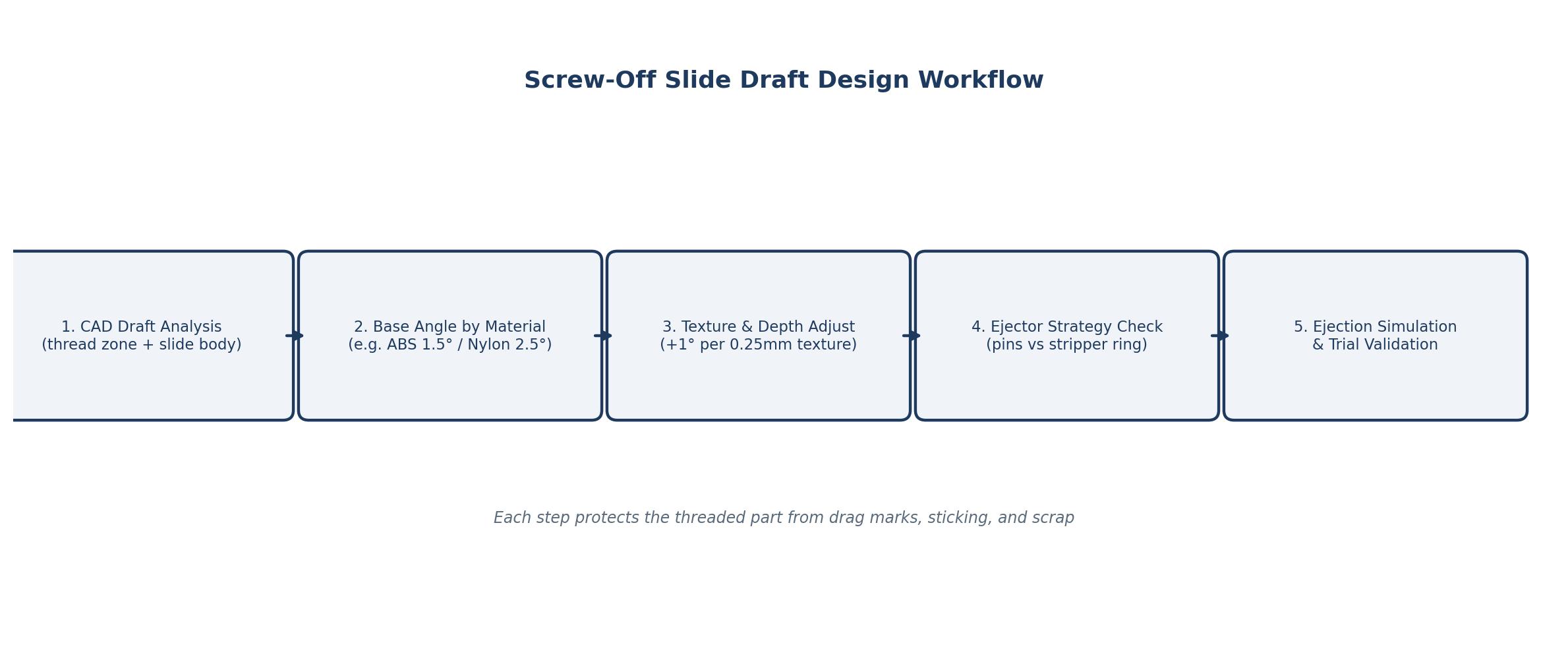
Start with a draft analysis in CAD before any steel is cut. Mold design software such as NX, Creo, or SolidWorks includes draft-angle inspection that colors every face by its angle relative to the parting direction. Run this analysis on the thread region, the slide body, and the mating cavity walls. Injection mold design reviews should treat the threaded zone as its own checklist item, separate from the general cavity draft pass. The same logic that guides mold base and insert selection applies when choosing how much taper the slide needs.
Next, set the base angle from the material table below, then adjust for texture and part depth. For a textured closure made of PP, for instance, begin at 2 degrees per side and add 1 degree for the texture. For deep threads over 10 mm of engagement, push toward the upper end of the range. If the part family includes both caps and jars, standardize the angle so the mold base and slides stay interchangeable.
Then verify the ejector strategy. Screw-off slides typically pair with lifters, stripper rings, or ejector pins arranged around the thread zone. The draft angle directly influences how much of the ejection load the pins carry. Larger draft reduces pin stress and spreads the load more evenly, which extends pin life on high-cavitation molds. On molds where a stripper ring carries the load, the ring contact face itself needs its own draft review. Detailed draft angle injection molding guidelines from production shops break these ejector interactions down further.
Finally, simulate the ejection phase with mold flow software. Ejection-force prediction confirms whether the chosen injection molding screw off slide draft angle keeps forces within acceptable limits. For medical or automotive parts with tight tolerances, this step separates a mold that runs for a million cycles from one that needs rework after the first pilot run. Simulation also catches cooling-related sticking, where the part has not fully solidified before the slide retracts, a failure mode no amount of draft alone can fix. Molders who run into sticking problems mid-production can reference this troubleshooting guide for molding defects while the tool is being reviewed.
Draft Angle by Material: A Practical Reference Table
The values below reflect typical production settings across the injection molding industry. They are starting points, not absolute rules. High-shrinkage materials such as nylon and glass-filled compounds sit at the upper end, while amorphous low-shrinkage resins tolerate shallower angles. When in doubt, mold designers default to 1.5 degrees per side on polished surfaces and add from there.
| Material | Recommended Draft (°/side) | Notes for Screw-Off Slides |
|---|---|---|
| Polyethylene (PE) | 0.5–1.5 | Low shrinkage, slippery; minimal taper on shallow threads |
| Polypropylene (PP) | 1–2 | Semi-crystalline; add 1° for texture |
| Polystyrene (PS) | 0.5–1.5 | Amorphous, rigid; keep flanks clean |
| ABS | 1–2 | Good release; 1.5° typical for cosmetic parts |
| Nylon (PA6/PA66) | 2–3 | High shrinkage, strong grip; core side up to 3.5° |
| POM / Acetal | 1.5–2.5 | Moderate shrinkage; watch thread root radius |
| Glass-filled (30% GF PA) | 2.5–3.5 | Abrasive to steel; larger draft reduces wear |
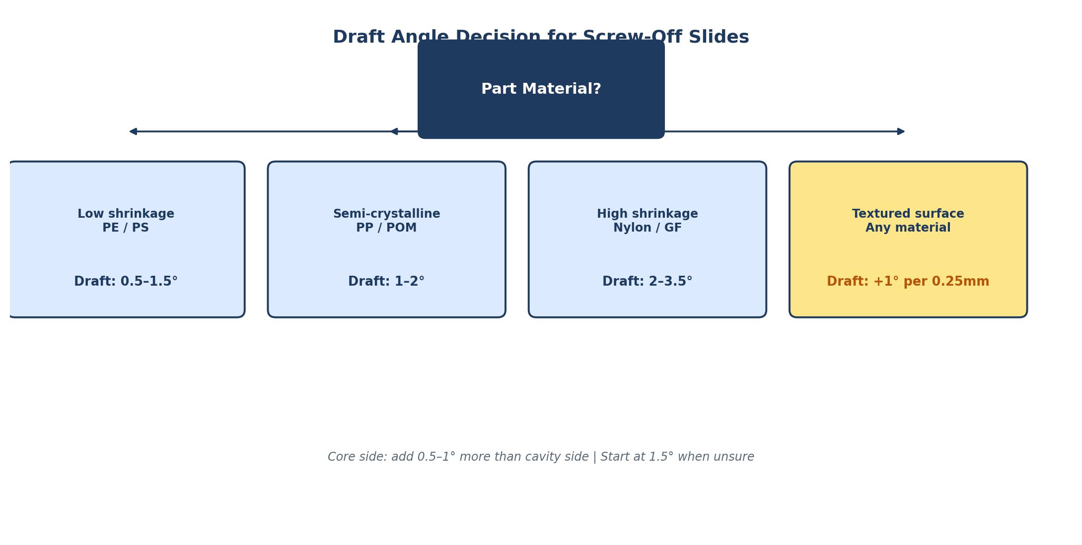
5 Screw-Off Slide Draft Mistakes That Wreck Production
Mistake one is zero draft on the thread flanks. Designers sometimes copy a machined thread profile straight into the mold without taper, reasoning that the thread is what it is. On the slide, those vertical flanks bind against the shrinking part and produce drag marks on every shot. Adding 0.5 to 1 degree to the non-functional flank fixes most of these cases. Getting this right from the start also avoids the kind of hot runner and gating complications that show up when a threaded tool cannot cycle smoothly.
Mistake two is ignoring texture depth. A fine cosmetic texture of 0.5 mm on a closure cap adds mechanical interlock that feels like twice the shrinkage. The rule of thumb holds: 1 degree per 0.25 mm of texture depth. Underestimate it and the first sampling run delivers stuck parts and polished-away texture, followed by an expensive rework cycle on the slide steel.
Mistake three is drafting in the wrong direction. Inverted taper on the slide face creates a secondary undercut that locks the part to the tool. Draft analysis flags this immediately, yet it still slips through when the slide geometry is modeled as a separate body and checked out of context. The fix costs real money because it requires re-cutting the slide surface after hardening.
Mistake four is uniform draft across core and cavity. Copying one angle to both sides ignores the shrinkage grip on the core. The part contracts onto the core, so the core side needs the larger angle. Using the same angle on both sides leaves the core side borderline and pushes ejection force up, which shortens ejector pin life on high-cavitation molds.
Mistake five is treating the ejector system as an afterthought. Screw-off slides often share space with lifters and pins, and cramped ejection layouts force small-diameter pins that gall and break under high force. Correct draft angle reduces the force requirement, letting the ejector layout use fewer, larger pins with better service life. A mold that runs 24/7 production will show the difference in maintenance frequency within the first few months.
| Common Mistake | Consequence | Fix |
|---|---|---|
| Zero draft on thread flanks | Drag marks, scuffed threads | Add 0.5–1° to non-functional flank |
| Ignoring texture depth | Sticking, texture loss | +1° per 0.25 mm texture depth |
| Inverted draft direction | Hidden undercut, locked part | Re-run draft analysis on slide body |
| Uniform core/cavity angle | High ejection force, pin wear | Core side +0.5–1° vs cavity |
| Ejector layout afterthought | Gall, broken pins | Size pins for reduced ejection load |
How Much Does Bad Screw-Off Slide Draft Cost?
Tooling rework is the obvious cost. Re-cutting a hardened slide to add draft means EDM or milling work, re-polishing, and re-fitting, typically several thousand dollars per slide plus lost production time while the tool is down. The less obvious cost is scrap. A 32-cavity cap mold running at 20-second cycles produces over 5,000 parts per hour; a 5 percent drag-mark defect rate burns through hundreds of parts per shift before anyone notices the pattern.
There is also the cost hidden in ejector maintenance. Pins, stripper rings, and slide wear plates all degrade faster when the part fights the tool on every cycle. Molders who track maintenance spend per shot see a measurable gap between tools designed with disciplined draft and tools where draft was an afterthought. For a mold expected to run millions of cycles, the injection molding screw off slide draft decision made at design time is the cheapest insurance available.
Application Scenarios: Where Screw-Off Slides Earn Their Keep
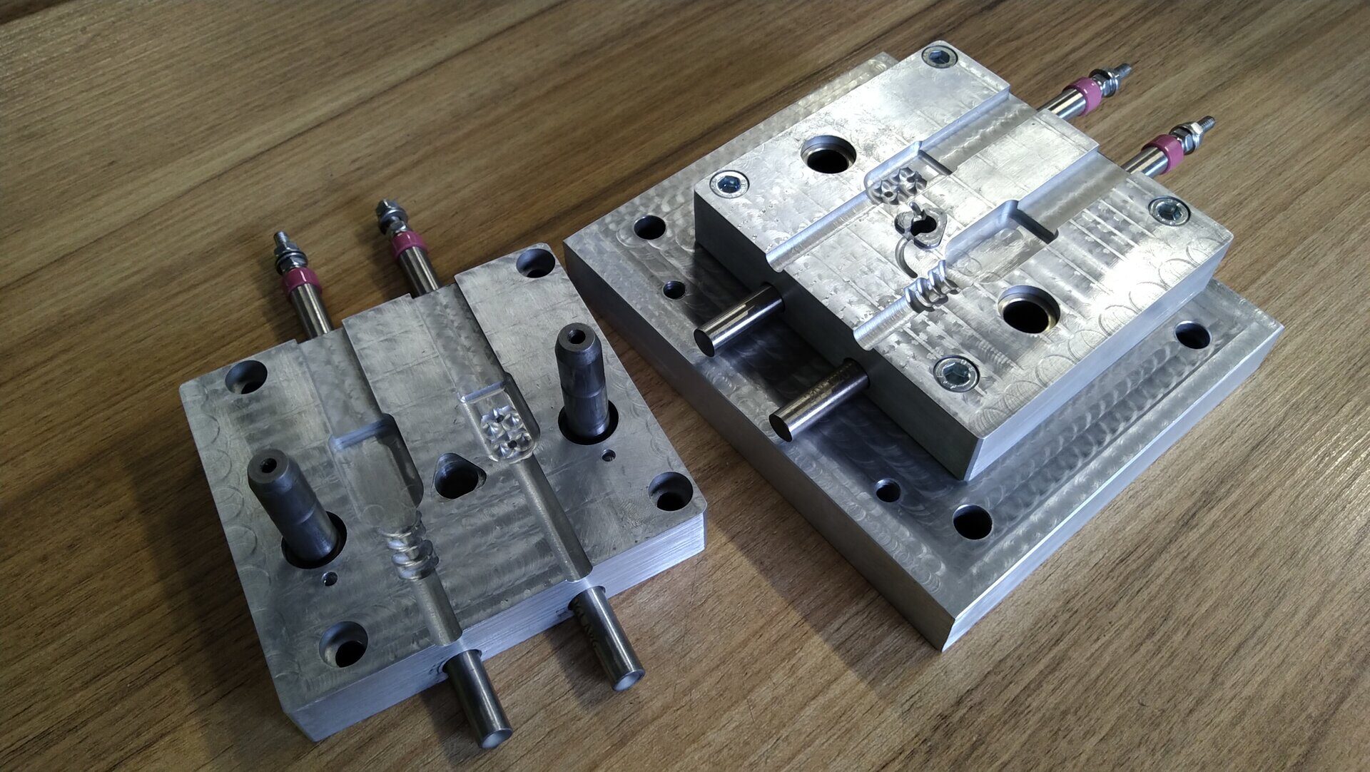
Packaging is the biggest user. Soda bottle caps, cosmetic jar lids, and flip-top closures all rely on screw-off slides or unscrewing molds to form external threads. Packaging runs at extreme cavitation, so draft discipline directly translates into uptime. A cap mold with correct draft runs hours without operator attention; one with marginal draft needs constant babysitting. On multi-cavity tools, a thermolator or temperature control unit keeps the slide and thread zone at stable temperatures, which also reduces sticking.
Medical devices form the second major family. Luer locks, syringe components, and IV connectors carry thread forms with tight dimensional requirements and clean-room constraints. Servo-driven unscrewing systems dominate this sector because they offer torque control and clean operation, but screw-off slides still appear on external thread forms where part geometry allows. Draft here protects the sterile surface finish as much as the thread form itself.
Automotive and plumbing round out the picture. Fluid reservoir caps, sprinkler heads, and irrigation fittings are molded in volume with sliding core action. These parts often use glass-filled resins that abrade the slide steel, and larger draft angles meaningfully extend tool life between maintenance stops. Molders running these parts pay attention to the draft table because they see the wear data directly. The same material logic drives material selection for automotive injection molding, where glass-filled grades are common on threaded fasteners.
Adjusting for Ejectors, Texture, and Core-Side Geometry
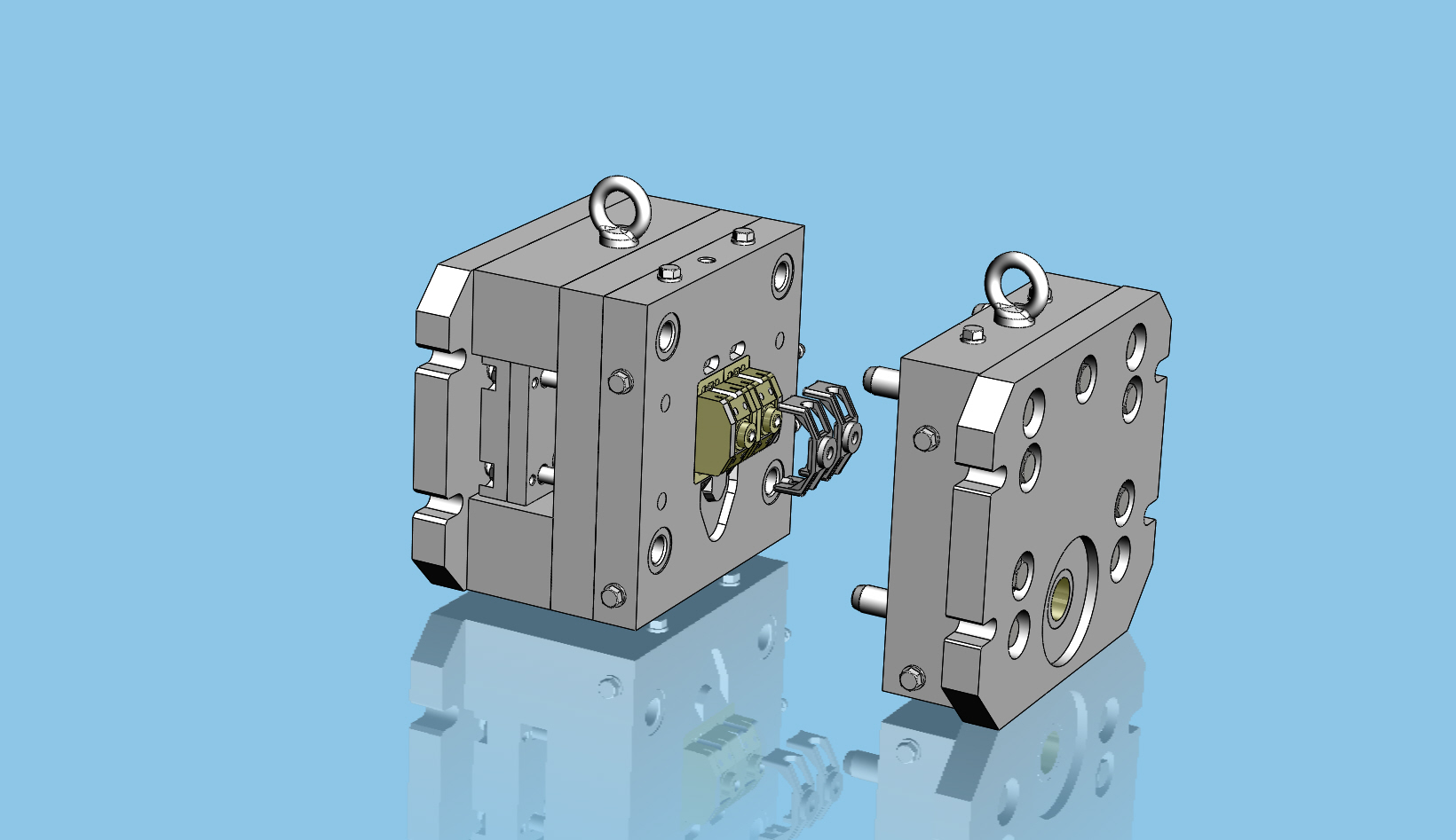
Ejector placement interacts with draft more than most designers expect. Pins positioned inside the thread zone push directly against the part wall, and the draft angle determines how much of that push converts into release versus pure friction. On deep threads, a stripper ring that pushes the part periphery while the slide retracts outperforms pin-only layouts.
Texture on threaded parts deserves special care. Mold texturing of the slide face changes the effective friction coefficient across the entire engagement area. When a customer requests a matte or leather-grain finish on a threaded cap, the draft must increase before texturing, not after the texture has already locked the surface into place. Draft requirements for injection molded parts always escalate with texture depth, and threaded surfaces are no exception. Suppliers of unscrewing mold systems publish similar guidance for their rotating-core tools.
Core-side geometry on screw-off slides also includes the undercut relief. The area behind the thread form, where the slide carries the lug or bayonet feature, needs its own draft review. Undercut features on the slide increase required draft by forcing the part to flex or compress during retraction, and a shallow angle here leads to ejection marks on the relief surface. Collapsible core molds solve similar internal-thread problems with a different mechanism, but the draft logic on the collapsible segments follows the same material and texture rules. For smaller threaded components, micro mold design applies the same draft discipline at a much finer scale.
Frequently Asked Questions
What is the standard draft angle for a screw-off slide?
Most production molds run 1 to 3 degrees per side on screw-off slide surfaces, with the core side 0.5 to 1 degree higher than the cavity side. Deep threads, textured surfaces, and high-shrinkage materials push toward the upper end of that range. When the injection molding screw off slide draft angle lands below 1 degree, expect sticking on rigid resins.
Can a screw-off slide have zero draft?
Technically a zero-draft thread flank can eject if the material is flexible enough to stretch, but production reliability drops sharply. Rigid resins like ABS or polycarbonate on vertical flanks almost always produce drag marks. A minimum of 0.5 degrees per side is standard practice.
Does texture affect screw-off slide draft requirements?
Yes, significantly. Textured mold surfaces interlock with the plastic mechanically. Add roughly 1 degree of draft for every 0.25 mm of texture depth. A 0.5 mm leather-grain texture on a part that normally needs 1 degree requires at least 3 degrees per side.
What happens if the draft angle is too large?
Excess draft thins the part wall unevenly, wastes material, and can cause assembly fit problems for parts that mate with other components. Above 5 degrees per side is rarely necessary except for very deep draws or heavy textures.
How does a screw-off slide differ from an unscrewing mold?
A screw-off slide retracts laterally to release external threads, while an unscrewing mold rotates the core with a gear, rack, or servo drive to disengage internal threads. Screw-off slides are simpler and lower cost for external thread forms; unscrewing molds handle internal threads and higher volumes.
Why do threaded parts stick to the slide even with correct draft?
Sticking usually traces back to shrinkage grip, insufficient cooling before ejection, or a mold surface that needs polishing or chrome plating. Check the draft angle first, then verify the ejection temperature window and the slide surface finish.
What materials need the most draft on threaded parts?
Nylon and glass-filled compounds grip the steel hardest and need 2 to 3.5 degrees per side. Polyethylene and polystyrene need the least, around 0.5 to 1.5 degrees. High-shrinkage semi-crystalline resins always sit above the amorphous group on the draft table.
Should draft angle change when moving from a slide to an unscrewing mechanism?
Yes. Unscrewing molds rotate the core out of the thread, so the thread flanks themselves carry less ejection load and flank draft matters less. The outer surfaces still need standard draft, and the rotating core requires polished flanks to avoid thread tear-out during the unscrew cycle.
Conclusion
The injection molding screw off slide draft angle is a small number that carries outsized consequences. Get it right and the mold cycles cleanly for years; get it wrong and every shot pays for the mistake in drag marks, scrap, and downtime. Start with the material-based angles in the table above, add texture and core-side adjustments, verify with draft analysis and ejection simulation, and review the five mistakes before the tool goes to sampling. Threaded parts are some of the most profitable components a mold shop runs, and draft discipline is what keeps them profitable.