
Sixteen zones, one controller, and the same relay keeps dying on zone 7. The maintenance tech swaps it, the new one lasts three weeks, and the part number matches the drawing every time. When a solid state relay fails like that, the relay is usually the last thing that should be replaced first. The cabinet is already telling you something about current, heat, or the load.
This guide is about reading those signals before the next relay goes in. Load current, cold-start surge, the real temperature inside the panel, the wiring around the control input—those are the numbers that decide whether the part lasts three months or eight years. TOPOWER, the team behind cntopower.com, builds hot runner controllers and the panels around them, so most examples here come from heater zones, thermocouples, and the relays that switch them.
In this guide: what the relay does · how it switches AC · seven specifications · sizing for real current · heat sinking · wiring · SSR vs contactor · who buys · TOPOWER hot runner panels · troubleshooting · market data · trends · FAQ · supplier checklist
What a Solid State Relay Does in a Heater Panel
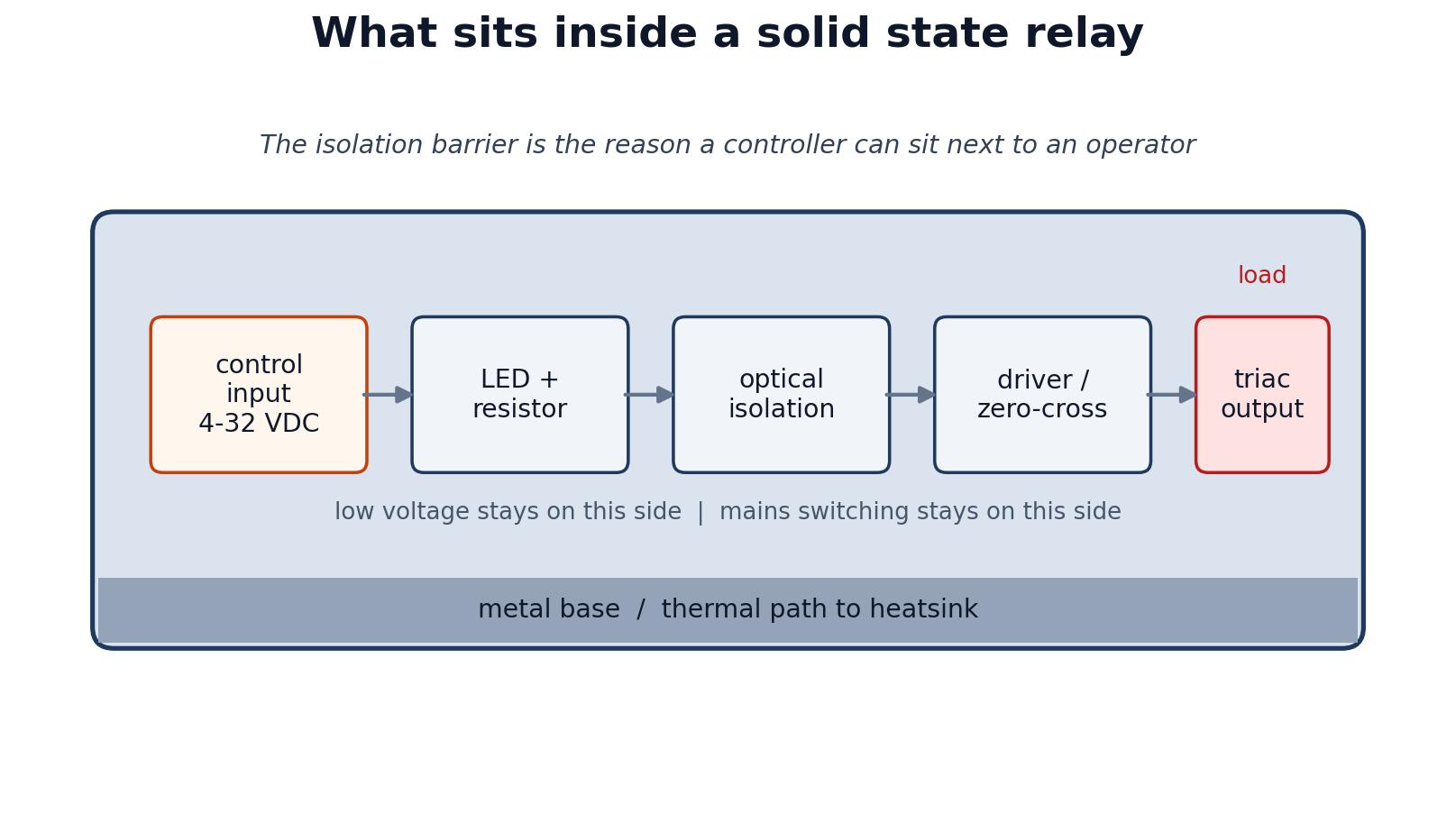
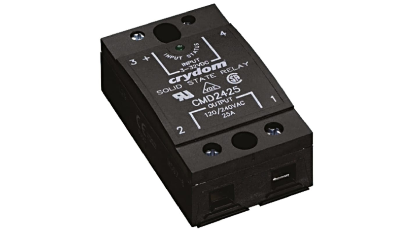
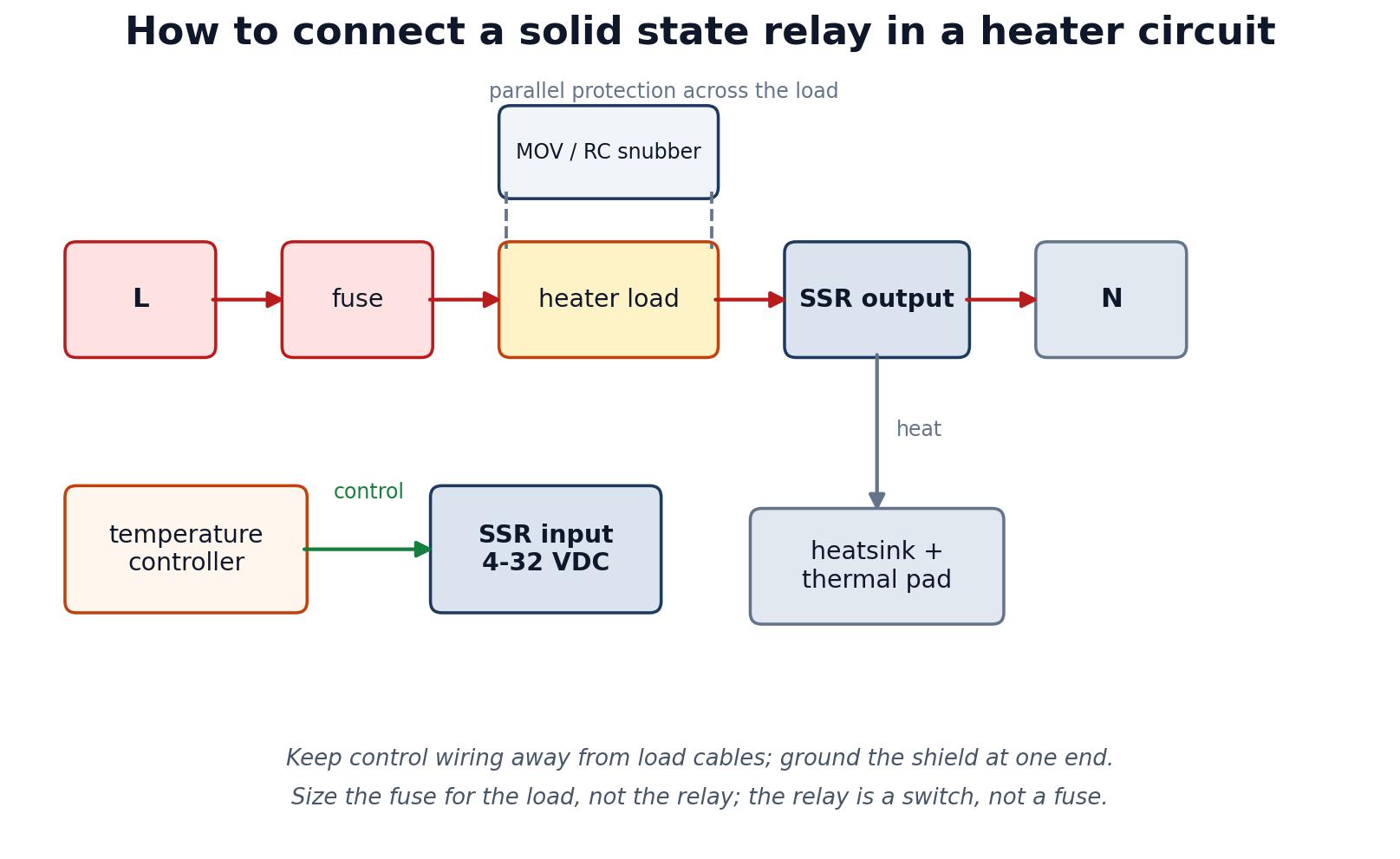
A solid state relay is a switch with no moving parts. A small control voltage—4 to 32 VDC on most panel models—drives an input circuit, and an output semiconductor connects or disconnects the load. In a heater panel that load might be a band heater, a cartridge heater, a hot runner nozzle, or a bank of infrared lamps.
The input and output sides of a solid state relay are isolated, usually by an optocoupler. That is what lets a digital temperature controller sitting at 24 V share a cabinet with a 480 V heater circuit without a common ground. The basic construction has not changed much in years, but the thermal limits still catch people out.
No coil, no armature, no arc.
That means no contact wear and no click to listen for. A relay that is working and a relay that is off can sound exactly alike, so commissioning usually comes down to an LED, a current clamp, or the controller's output status.
The price of all that silent switching is heat.
A thyristor output drops somewhere around 1 to 1.6 V. Put 20 A through it and you get roughly 30 W inside a package the size of a card deck. The only way out is through the metal base. If the mounting surface cannot take that heat away, the junction temperature climbs and the semiconductor eventually fails—often shorted, which is the failure mode nobody wants in a heater circuit.
How It Switches AC Power
Most AC solid state relays switch with a triac or a pair of thyristors. An LED on the input shines through an optocoupler onto a phototriac or driver, and the output is allowed to conduct while the control signal is present. Take the signal away and an AC output keeps conducting until the current crosses zero. Not instantly. That distinction explains a lot of field behaviour.
It is why a solid state relay rated for AC cannot interrupt a DC load—the current never crosses zero, so the device never turns off.
It is also why a meter with high input impedance can show voltage across a load that is supposedly off; the snubber network is passing a small current. Neither is a defect. Texas Instruments goes through the isolation and output topologies in detail, and Electronics Tutorials has a clear waveform walk-through.
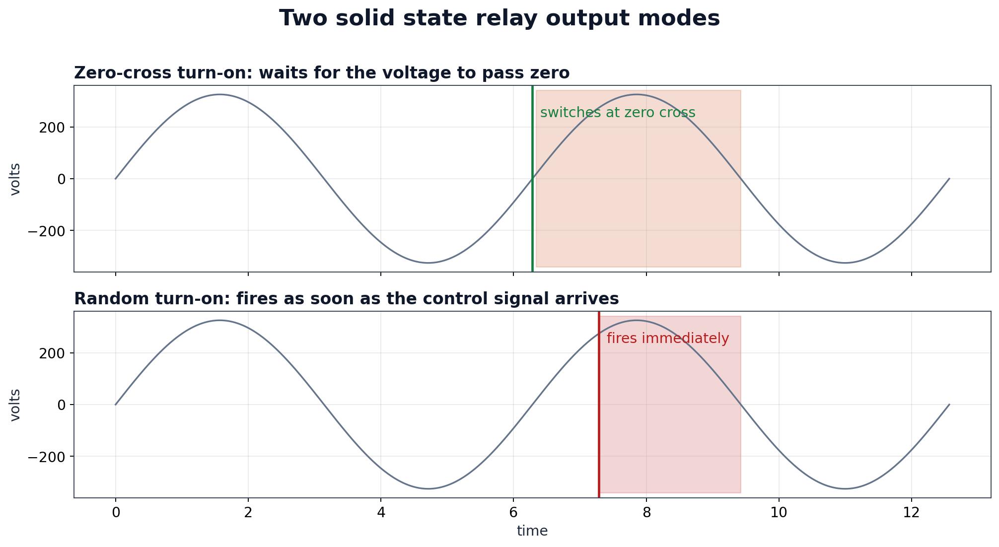
A zero-cross solid state relay waits for the mains to pass near zero before it turns on.
That cuts the current step and the electrical noise from switching a resistive heater at some random point in the cycle. Random-turn-on versions fire as soon as the signal arrives, which suits inductive loads and phase-angle control. Heater panel? Zero-cross is almost always the right default. Motor or transformer? Different conversation.
DC versions use MOSFETs or IGBTs and can switch at any point in the cycle. Solenoid valves, DC heaters, battery circuits. The ratings still need checking, but against a DC source rather than an AC waveform, and reverse-voltage protection becomes part of the selection.
Seven Specifications That Decide the Model
Choosing a solid state relay can eat an afternoon in a data sheet. Seven numbers usually settle it: load voltage, rated current, surge current, control input, output type, mounting, and the ambient/derating curve. The same part may be sold as a solid state relay, a semiconductor relay, or an SSR relay, and the labels are not used consistently. The numbers are.
| Specification | What to check | Common mistake |
|---|---|---|
| Load voltage | AC or DC, nominal and maximum, including supply tolerance | Using a 240 V part on a 480 V circuit, or an AC part on DC |
| Rated current | Steady-state current at the real ambient, then derate | Reading the headline rating at 25 °C and running at 60 °C |
| Surge current | Cold heater inrush, motor starting current, lamp surge | Sizing only for the nameplate running current |
| Control input | 4–32 VDC, 90–280 VAC/DC, input current and threshold | Driving a 4 mA input from a PLC output rated for 2 mA |
| Output type | Zero-cross or random turn-on; single-phase, three-phase or DC | Zero-cross on a phase-angle controller or an inductive load |
| Mounting | Panel, DIN rail, PCB; terminal size and torque | Ignoring clearance and the heatsink footprint |
| Ambient and derating | Current-versus-temperature curve for the real cabinet | Using the 25 °C rating in a sealed enclosure |
For a solid state relay, load voltage needs headroom for transients, not just the RMS supply. A 240 V line can throw spikes well above its nominal value. Most AC outputs are rated at 280, 480, or 600 V; pick the band above the supply. On 380–480 V systems, 600 V is the common choice.
Current is where the trouble usually starts.
A 25 A solid state relay is a 25 A device at a defined case temperature—often 25 °C—with a specified heatsink. A Crydom solid state relay data sheet is a useful reference for how quickly that rating falls with mounting and ambient. In a closed panel at 50 °C, a 25 A part may only be good for 15 A. A 40 A relay for a 22 A heater is not overkill; it is the honest number.
The control side belongs in the same conversation. The temperature controller selection guide covers output type, sensor input, and alarm strategy. What matters here is simpler: can the controller output actually drive the relay input? A 4–32 VDC input that draws 10 mA will not switch reliably from a PLC output rated for 2 mA, no matter how good the relay is.
Sizing for Real Heater Current
Sizing a solid state relay starts with the heater at the voltage it will actually see. A 3 kW heater rated at 240 V draws 12.5 A. On a 230 V supply it draws about 11.5 A, because resistance is roughly fixed. On 250 V it draws closer to 13 A. The nameplate wattage is not a current rating, and the supply is rarely exactly nominal.
Then account for cold starts. A resistive heater has lower resistance when cold, so the first cycles can pull about 1.4 times the running current. That 12.5 A heater may briefly draw 17 A. The relay's surge rating has to cover it, and the branch protection has to ride through it without tripping. Motors are worse—four to eight times running current—which is why motor circuits usually need a larger relay or a different switching device altogether.
A sensible starting point is 70 % of the relay's rated current for a resistive heater, and around 50 % for inductive or motor loads. Those are starting points, not guarantees. The manufacturer's current-versus-ambient curve wins, and when several relays share one heatsink, each one heats the others.
Switching frequency matters too. Time-proportioning controllers may cycle a heater every few seconds. A solid state relay handles that without contact wear, but the thermal cycling still works on the semiconductor and the solder joints. A solid state relay sized with margin runs cooler per cycle and usually lasts longer. The extra cost is small next to a stopped line.
Heat Sinking, Mounting and Panel Layout
Most solid state relay failures are thermal, and most of the heat is generated inside the relay.
The metal base is the only practical exit. Mount it on a flat metal surface with thermal compound or a pad, then torque the screws to the supplier's number. M4 terminals are often 0.98–1.37 N·m; M3, about 0.56–0.98 N·m. Loose screws add resistance and heat. Too much torque can crack the internals.
Above 10 A, use a solid state relay heatsink.
Above roughly 100 A, forced air or a larger assembly is usually necessary. A plain aluminium plate can work at low current: 150×150×3 mm is around 4 °C/W, 300×300×3 mm around 2 °C/W. Painted steel is not a substitute.
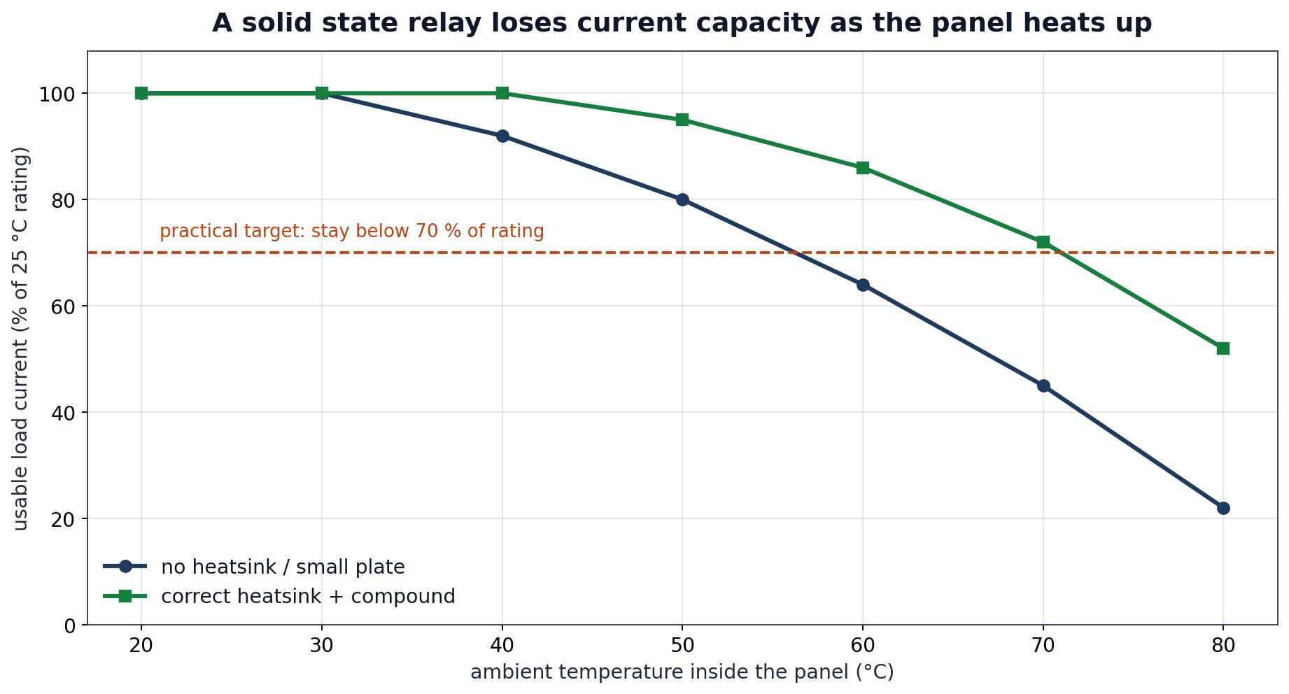
The enclosure matters as much as the heatsink.
A relay that runs at 45 °C on an open bench can pass 80 °C in a sealed cabinet next to transformers and power supplies. Keep the base below the manufacturer's limit—often 85 °C—and aim lower. Leave space between relays. Do not mount them above a brake resistor.
Hot runner cabinets are a particular case. The relay bank sits beside controllers and power supplies, and the hot runner controller accessories in the same space add their own heat. The cabinet needs an airflow path, not just a bigger plate under one relay.
Wiring and Protection
Separation first.
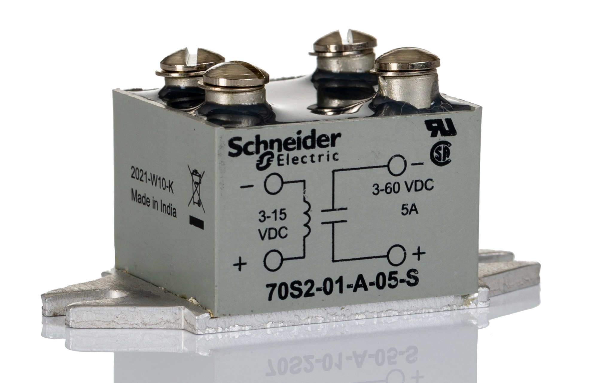
Run the control signal in shielded twisted pair, ground the shield at one end, and keep it away from load cables. A long unshielded control wire running parallel to a 480 V heater cable can pick up enough voltage to hold the relay on—or to trigger it when the controller says off.
Then protect the solid state relay output from the load's stored energy. DC coils get a flyback diode. AC coils and contactor coils get an RC snubber or a MOV. On 220 V, a 500–600 V varistor is common; on 380 V, 800–900 V. Short-circuit protection needs to be fast—a fuse or a fast breaker. The relay is a switch, not a fuse.
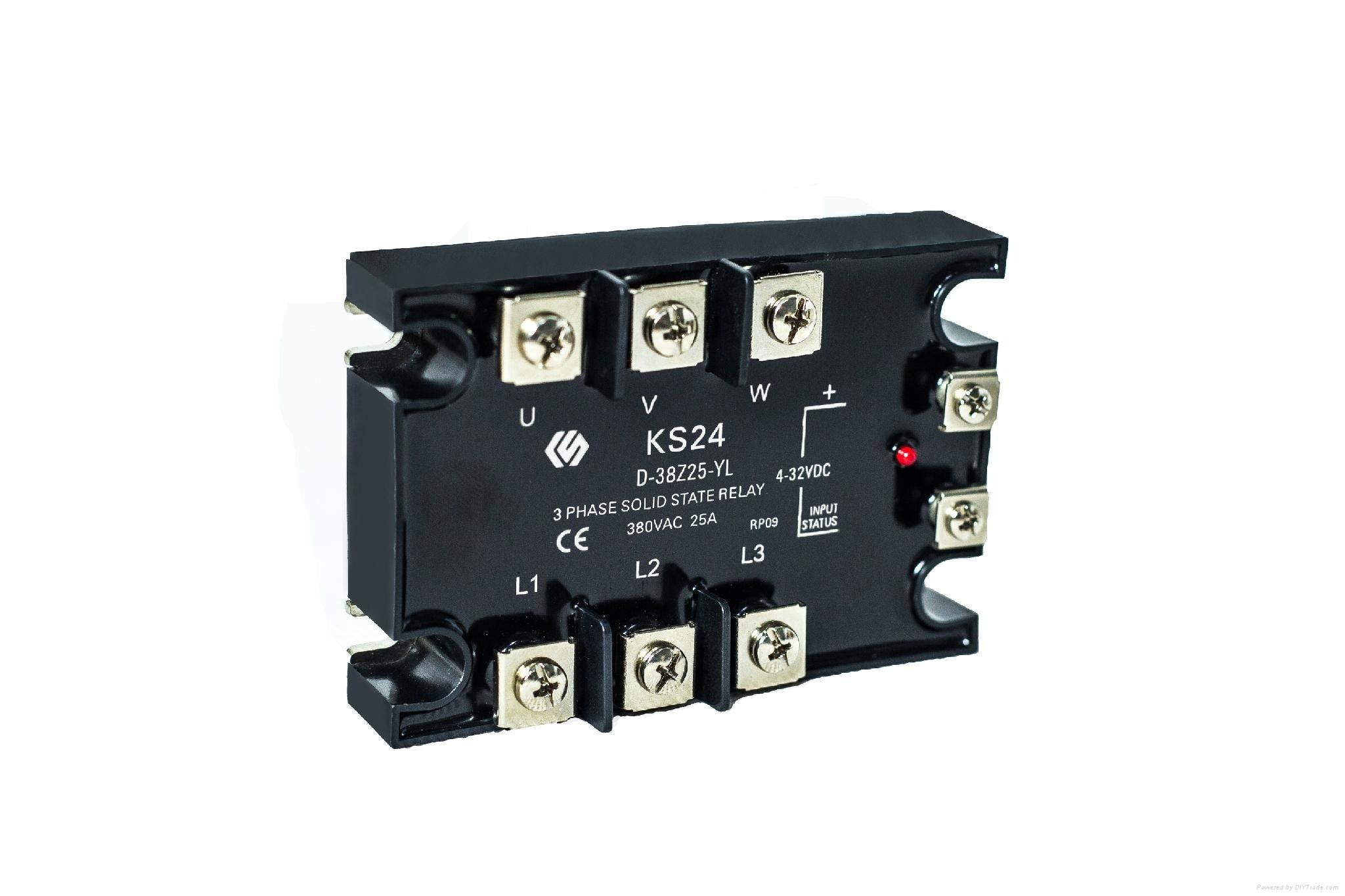
Off-state leakage deserves a plan; the solid state relay wiring diagram above shows where the bleed resistor goes.
A solid state relay may pass a few milliamps when it is off, and a snubber adds to that. On a high-impedance load, or one with an LED indicator, that can be enough to make the load glow or stay partly energised. A bleed resistor across the load, roughly eight to ten times the maximum leakage current, gives the current somewhere to go. If the circuit has to be truly dead when off, use a contactor or a disconnect ahead of the relay.
Check the control current at the actual controller output, not just on the data sheet. A 4–32 VDC input may draw 7–12 mA. Long wires add resistance. Several relays on one output add load. Measure it. The same discipline applies to self-regulating heat tracing, where long circuits and cold-start currents put similar demands on the switch.
Solid State Relay vs Contactor and Mechanical Relay
This is not a question of which device is newer.
It is a question of which failure mode the process can live with.
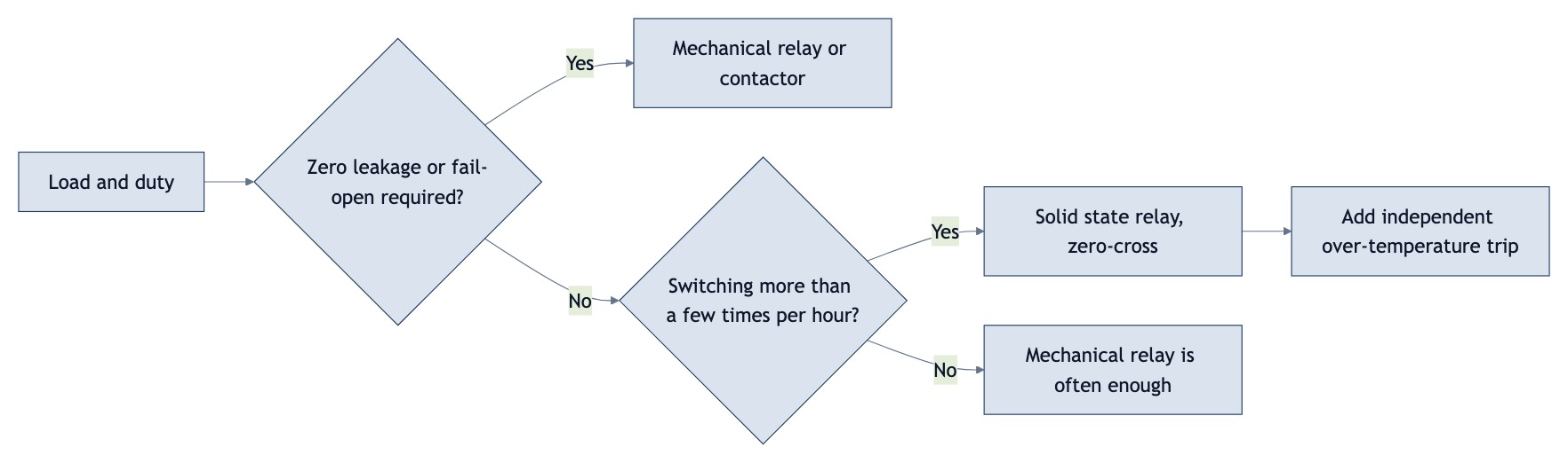
A mechanical relay or contactor opens an air gap and usually fails open. A solid state relay has no gap and often fails shorted, which means the heater can stay on. Small heater with independent over-temperature protection? Probably acceptable. Large hot runner or pressure vessel? It needs a second layer.
| Behaviour | Solid state relay | Mechanical relay / contactor |
|---|---|---|
| Switching life | Very high; no contact wear | Limited by mechanical cycles and load type |
| Off-state leakage | Small but present, often a few mA | Essentially none; true air gap |
| Typical failure | Often shorted, load stays energised | Usually fails open, but contacts can weld |
| Switching speed | Fast; suitable for time-proportioning control | Slower; contact bounce and arc erosion |
| Audible noise | Silent | Audible click |
| Heat generation | Needs a heatsink and panel space | Coil heat, usually less than an SSR |
| Best fit | Frequent switching, resistive heaters, clean panels | Isolation-critical circuits, low-current signals, fail-open duty |
Cost comparisons that stop at the purchase price miss half the panel. A solid state relay costs more, needs a heatsink, thermal compound, and space. What it does not need is a replacement every few months because the contacts wore out. On a high-cycle heater, the total cost usually favours the solid state part. On a few operations a day, it may not.
A solid state contactor is the same output principle at higher current, often with a built-in heatsink and a DIN-rail body. The thermal and failure-mode questions do not change. In a mould temperature controller, the relay is one part of a loop that includes the sensor, the controller, and the heater. The weakest part sets the reliability, and it is not always the relay.
Who Buys a Solid State Relay, and What Each Role Checks
Three people usually touch the same decision, and they read different parts of the same data sheet.
The equipment engineer starts with the load: heater resistance, supply voltage, cold-start current, and what the controller can actually output.
Then the thermal path—heatsink, ambient, clearance, airflow. A relay that passes the current calculation but fails the thermal one is still wrong.
Maintenance cares about the next failure.
Can the relay be swapped without pulling a DIN rail? Are the terminals reachable? Is the part number visible once the wire duct is closed? A part that is hard to test gets replaced on suspicion, and suspicion is expensive.
Buyers comparing a solid state relay look at the order code, the certification marks, and the lead time. UL recognition, CE marking, and a real derating curve matter more than a headline current number. So does a second source with the same footprint.
Panel builders and hot runner OEMs sit across all three roles. They buy in volume, test in a cabinet, and support the end user after commissioning. For them, a consistent relay family is worth more than a slightly cheaper one-off, because the wiring and heatsink design carries over from project to project. The applications page shows the mould, packaging, and heating jobs where that repeatability matters.
Why Hot Runner Panels Pair TOPOWER Controllers with SSRs
Hot runner panels are where the relay earns its keep.
A nozzle zone cycles power in short slices, sometimes several times a minute. A mechanical relay would be tired by the end of the month. A zero-cross solid state relay switches the resistive heater without contact erosion and without throwing a large transient into the thermocouple circuit.
TOPOWER builds the controller and the panel around that duty. The hot runner temperature controller range covers 1 to 120 zones, in two styles: plug-in modular modules for easy swaps, and a PLC touch screen for centralised operation and alarm visibility.
The TP01 modular controller comes in 1, 2, 4, 6, 8, 12, or 16 zone frames. If a module fails, it comes out without rewiring the panel. The HY20 touch screen controller is aimed at larger multi-zone systems where operators need one screen for temperatures, alarms, and settings.
On a TOPOWER panel, the solid state relay is chosen with the controller output, not added afterward. The controller drives the relay input, the relay switches the heater zone, and the thermocouple closes the loop. Match the three and the zone holds temperature without nuisance alarms. Miss one and the symptom shows up as overshoot, a stuck zone, or a relay running hot.
For export buyers, the main controller models come with CE/RoHS documentation, OEM logo and colour options, and a one-year warranty. A three phase solid state relay is the usual choice when one zone group draws more current than a single-phase part can carry. The hot runner controller guide goes deeper on zone count and wiring.
Failure Modes and a 6-Step Troubleshooting Sequence
When a zone misbehaves, the relay gets blamed first. Often it is the last thing that should be touched.
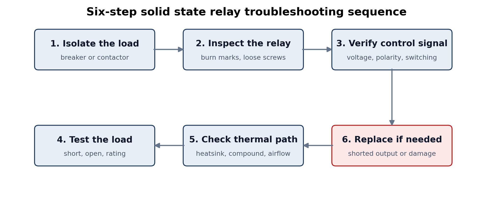
The Omron SSR FAQ covers the basic checks, and the hot runner controller troubleshooting guide handles the zone-level symptoms. The order matters: isolate, inspect, verify the signal, test the load, check the thermal path, then decide.
| Symptom | Likely cause | What to check |
|---|---|---|
| Heater stays on with no control signal | Output shorted; leakage; false trigger; AC relay on DC load | Output resistance with power off; leakage current; control wiring; load type |
| Heater never turns on | No control signal; reversed polarity; open output; blown fuse | Input voltage at the relay; polarity; fuse; load continuity |
| Relay runs very hot | Undersized heatsink; dry thermal compound; loose terminals; high ambient | Base temperature; mounting torque; heatsink size; panel airflow |
| Relay fails repeatedly | Inductive load without suppression; surge current; wrong derating | Snubber or MOV; cold-start current; ambient derating curve |
| Load glows when off | Off-state leakage through snubber | Leakage specification; bleed resistor; need for mechanical isolation |
Isolate the load with the upstream breaker first.
Do not trust a failed relay to be off. Then look for burn marks, discoloured terminals, cracks, or loose screws. Verify the control signal at the relay—voltage, polarity, and whether the controller output actually changes state. Test the load separately. Check the thermal path: heatsink, compound, torque, airflow, ambient. Replace the relay if the output is shorted, the on-state drop is excessive, or the part shows damage.
One more check on the sensor side. A loose or wrong K type thermocouple can make a healthy relay look faulty, because the controller keeps calling for heat. Verify the sensor before replacing the switch.
Market Data and What It Means for Buyers
The solid state relay market is growing steadily rather than exploding, and the mix is shifting toward semiconductor switching.
Straits Research puts the global market at about USD 1.52 billion in 2025 and USD 2.88 billion by 2034, a 7.4 % CAGR. Fortune Business Insights lands near USD 1.50 billion in 2025 and USD 2.80 billion by 2034, at 7.2 %. Research and Markets uses wider boundaries at USD 1.9 billion and USD 3.7 billion, 7.7 %. The absolute numbers differ; the direction does not.
| Source | 2025 size | 2034 forecast | CAGR |
|---|---|---|---|
| Straits Research | USD 1.52 bn | USD 2.88 bn | 7.4 % (2026–2034) |
| Fortune Business Insights | USD 1.50 bn | USD 2.80 bn | 7.2 % (2026–2034) |
| Research and Markets | USD 1.9 bn | USD 3.7 bn | 7.7 % |
| GII / VMR | USD 0.94 bn | USD 1.48 bn | 5.13 % (2026–2034) |
Asia-Pacific held about 45 % of the market in 2025, according to Straits Research. That fits the concentration of plastics, packaging, and electronics manufacturing in the region. North America is forecast at about 7.8 % CAGR. DC-output relays are growing faster than AC types, around 8.3 %, and EV charging is among the fastest-growing applications.
For a buyer, the headline number is less useful than the availability behind it. A solid state relay is a mainstream part now. Data sheets are detailed, second sources exist, and the difference between a good and a poor selection is mostly thermal design and load matching.
Key Trends Reshaping Solid State Relay Selection
Three shifts show up in the forecasts and in the parts catalogues.
DC output is growing faster than AC, around 8.3 % according to Straits Research, driven by battery systems, DC heaters, and electronics that no longer convert to AC just to switch a load. EV charging infrastructure is the fastest-growing application in the same forecast, near 9.1 %.
DIN-rail mounting with an integrated heatsink is the second. It saves panel space and removes a separate thermal assembly, but it also changes the derating calculation because the relay and the rail share heat. A convenient-looking part can run hotter than a panel-mount unit with a proper plate.
Three-phase and high-current assemblies are moving into cabinets that used to hold contactors. More heat in a smaller area makes airflow a design input. It also raises the value of a clear failure plan, because a shorted output on a high-current relay is harder to ignore than a small heater zone.
The heater side is changing too. Tubular heaters and ceramic heater bands are being specified with tighter watt density and faster cycles, which puts more demand on the switch. A relay chosen for the old duty cycle may not have the thermal margin for the new one.
Frequently Asked Questions
What is a solid state relay used for?
Switching a load with a semiconductor instead of moving contacts. In a heater panel it turns a resistive heater on and off under a temperature controller, often many times an hour. The same part shows up in motor circuits, lighting, battery systems, and test equipment.
How does a solid state relay work?
A control signal drives an LED inside the relay. The light crosses an optical barrier and turns on a driver, which lets the output semiconductor conduct. Remove the signal and an AC output waits for the current to cross zero before it stops conducting.
What is the difference between a solid state relay and a contactor?
A solid state relay has no moving contacts and switches frequently without wear. A contactor has an air gap, essentially no off-state leakage, and usually fails open. Use the solid state part for time-proportioning heater control; use the contactor where isolation and high fault current matter more than switching life.
Does a solid state relay leak current when it is off?
Yes, a small amount—often a few milliamps through the output semiconductor and snubber. On a high-impedance load that can be enough to make an indicator glow. A bleed resistor across the load usually fixes it.
Does a solid state relay need a heatsink?
Above about 10 A, yes. The output device dissipates power, and the metal base is the path out. Flat surface, thermal compound, correct torque, and a current rating derated for the real ambient.
Can a solid state relay switch DC?
Only a DC-rated one. An AC output, especially zero-cross, relies on the current crossing zero to turn off. A DC load never does, so the output may stay on. Use a DC relay with MOSFET or IGBT output and check the reverse-voltage rating.
Should I choose zero-cross or random turn-on?
Zero-cross for resistive AC loads such as heaters, especially with on/off or time-proportioning control. Random turn-on for inductive loads, phase-angle control, or when the switch has to act immediately.
How do I know if a solid state relay has failed?
Remove the control signal, isolate the load, and measure the output. Very low resistance or a load that stays energised points to a shorted output—the most common failure. With the signal applied, the output should conduct.
Can two solid state relays be connected in parallel?
Not by simple paralleling. The devices will not share current evenly, and one may carry most of the load. Use a relay rated for the total current, or follow the manufacturer's balancing guidance.
Why do hot runner systems use solid state relays?
Because the zones switch often. A mechanical relay would wear out; a solid state relay handles the cycles without contact erosion. It still needs independent over-temperature protection, since it can fail shorted.
Choosing a Supplier: What to Send Before You Ask for a Quote
A solid state relay is a commodity part. The panel around it is not. A supplier who can match the controller, the relay, the thermocouple, and the wiring saves more time than a lower relay price—and the quote request is where that starts.
Send six things: the number of heater zones, the mold or machine type, the supply voltage, the preferred controller type, the thermocouple type, and whether accessories or OEM branding are needed.
Those six answers let a supplier propose a configuration instead of a catalogue number.
TOPOWER works through that sequence—confirm the zone count, match the controller and relay, prepare stock and export packing, then support the panel after commissioning. The company ships to more than 20 countries, offers CE/RoHS documentation on main controller models, and does OEM logo and colour work for distributors and hot runner system companies. The quality and capability page covers the manufacturing side.
Ask for the current-versus-ambient curve, not just the headline current. Ask which relay family comes with the controller, and whether the heatsink is included or sized separately. Ask for the wiring diagram for the exact zone count. A supplier who answers those three questions quickly is easier to work with than one who only quotes a price.
For a hot runner panel, send the zone list and thermocouple type with the inquiry. That is enough for a first configuration. Start at the TOPOWER contact page, or look through the product range before the call.
Final Thoughts
A solid state relay is a simple part with a narrow thermal budget.
Load voltage, real current, surge, ambient, heatsink, and a plan for the failure mode you cannot avoid—that is most of the selection.
Calculate the current at the actual supply. Add the cold-start surge. Apply the derating curve for the real cabinet. Confirm the control source can drive the input. Then mount it properly and record the base temperature at commissioning. Those steps take less than an hour and remove most of the reasons a relay dies early.
The goal is not the biggest relay on the shelf.
It is the relay that runs cool, matches the controller, and has a plan for the day it fails. TOPOWER builds panels around that idea, and the contact page is the place to start a configuration.