Brass pipe nipplesIntroductionBrass pipe nipples are short sections of brass tubing with male t...
How to Diagnose and Fix Thermocouple Failures: A Practical Troubleshooting Guide
2025-11-24
Introduction
Thermocouples are trusted for industrial temperature measurement because they are rugged, fast, and reliable. However, harsh conditions—vibration, moisture, corrosion, and wiring issues—can cause inaccurate or unstable readings.
This guide provides a complete, field-ready method to diagnose and solve thermocouple faults. It integrates common industrial failure modes such as drift, moisture intrusion, poor contact, installation errors, and compensation-wire mismatches. Use this article as a troubleshooting manual to restore accurate measurement and reduce process downtime.
Why Thermocouple Type Matters
Before troubleshooting, always confirm the thermocouple type (K, J, T, E, S, R, B).
Using incorrect extension cables, mismatching instrument settings, or exposing certain types to inappropriate atmospheres can generate large reading errors.
Common Thermocouple Symptoms and Their Root Causes
Below is a practical breakdown of typical symptoms and what usually triggers them.
Reading Lower Than Actual Temperature (Indication Too Low)
Possible causes
Sensor degradation or oxidation at the hot junction
Over time, the tip may deteriorate or become contaminated, leading to lower EMF output.Moisture inside the protection tube or insulation
Damp insulation increases leakage paths and reduces the signal.Dust, debris, or metal particles inside the connection box
Conductive contaminants can create partial short circuits.High circuit resistance
If wiring resistance exceeds typical limits (often around 10–15 Ω), signal loss increases.Compensation cable issues
Moisture intrusion or short circuits between wire and protection tube.Incorrect extension wire type
Using a mismatched grade or non-thermocouple wire shifts the measured value.Shallow insertion depth
The junction must be fully inside the active temperature zone.Cold junction too warm or unstable
High ambient temperature around terminals shifts the reference temperature.
How to fix
Replace or re-weld the junction if the sensing tip is damaged.
Dry the insulation, sheath, and junction box thoroughly.
Clean out the terminal area and ensure the outlet points downward to avoid moisture entry.
Measure circuit resistance; replace wiring if excessive.
Replace compromised compensation cables and improve waterproofing.
Ensure extension wires match the thermocouple type.
Increase insertion depth (typically ≥ 8 times the sheath diameter).
Move the cold junction to a cooler and stable location using proper compensation cable.
Reading Higher Than Actual Temperature (Indication Too High)
Possible causes
Instrument set to the wrong thermocouple type
Extension wire mismatched to the sensor
Sensor positioned too close to the heat source, not in the representative zone
How to fix
Reconfigure instrument input type
Install correct matching compensation wire
Adjust the probe position to a more representative location
Reading Is Unstable or Fluctuating
Possible causes
Loose terminal screws
Intermittent insulation breakdown causing periodic shorting or grounding
Excessive vibration causing unstable contact
Electromagnetic interference (EMI) from power cables, motors, or VFDs
How to fix
Tighten all terminals and clean contact surfaces
Identify insulation failure points and replace damaged components
Secure the probe or add vibration-damping brackets
Add shielding, grounding, or reroute wiring away from power lines
No Signal Output / Sensor Not Responding
Possible causes
Short circuit in the measuring loop
Broken wire or open circuit along the cable
Loose terminals
Completely burned or melted thermocouple tip
How to fix
Re-insulate or replace shorted sections
Perform continuity tests to locate open circuits
Tighten all terminals
Replace the thermocouple if the junction has failed

Step-by-Step Troubleshooting Procedure
Below is a structured, field-tested method combining practical checks with professional diagnostics.
Initial Inspection
Verify safety and isolate the sensor.
Inspect for mechanical damage—bent probes, crushed cable, cracked insulation.
Check for contamination—dust, metal shavings, fluids inside the connection box.
Confirm proper installation depth—too shallow results in the wrong temperature zone.
Electrical Tests
Continuity Test
Use a multimeter to verify the circuit is not open or shorted.
Loop Resistance Test
Excessive resistance suggests corrosion, poor connections, or degraded wiring.
mV Output Test
Compare measured mV with standard thermocouple tables to detect drift or offset.
Cold Junction Verification
Ensure CJC sensor is functioning and ambient temperature is stable.
Wiring & Cable Validation
Check polarity (+ / – must not be reversed).
Ensure extension cables match the thermocouple type.
Look for moisture intrusion causing leakage paths.
Ensure proper shielding and routing away from power cables.
Substitution Testing
To differentiate sensor failure from instrument failure:
Replace the thermocouple with a known-good probe.
Or connect a thermocouple simulator to the controller.
If the controller reads correctly with a simulator, → sensor or wiring is faulty.
Preventive Maintenance Tips
To avoid future failures:
Keep terminal boxes dry and downward-facing.
Inspect regularly for signs of corrosion or thinning of the sheath.
Avoid routing thermocouple cables with high-current lines.
Use appropriate protective sheaths for corrosive or high-temperature environments.
Establish a periodic calibration schedule, especially for high-temperature processes.
Summary
Thermocouples are reliable but can fail due to moisture, wiring errors, poor installation, or sensor degradation. By combining quick visual inspections, electrical checks, proper wiring validation, and calibrated replacement probes, you can diagnose most failures quickly and restore stable temperature measurement.
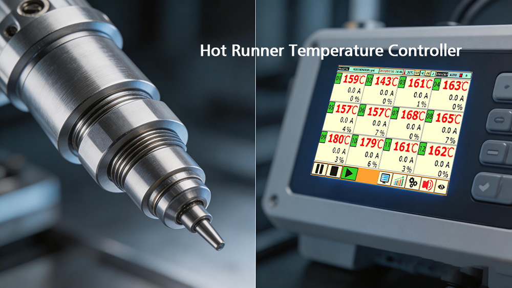
CNTOPower provides professional temperature control solutions designed for hot runner systems and industrial molding applications. If you need stable, precise temperature control with multi-zone capabilities, explore our industrial temperature controller solutions.