
Why Fixture Tolerance Standards Matter
A fixture tolerance standard keeps every part a fixture locates consistent — run after run, shift after shift. When a machining fixture holds a blank to loose tolerances, every part it produces inherits that error. Tighten the fixture tolerance standard and the whole process tightens with it.
Machining fixtures position and clamp workpieces so cutting tools machine them to print. If the fixture itself is out of tolerance, no amount of machine calibration fixes the result. That is why experienced shops define a fixture tolerance standard before designing any jig, welding fixture, or inspection fixture — and why automotive suppliers treat check fixture tolerances as contractual requirements.
This guide covers what fixture tolerance means, the standard values used across industry, how to apply them, and where the common pitfalls hide. It is written for machinists, fixture designers, and engineers who quote or build jigs — with reference numbers you can use directly in your own fixture tolerance standard.
Whether you are building a one-off drilling jig or a full automotive check fixture, the same principles apply. The difference is only in the numbers and the verification rigor. Start with the basics, then tighten where your parts demand it.
What Is a Fixture Tolerance?
Fixture tolerance is the allowable variation in the locating and clamping features of a fixture. It defines how accurately the fixture's pins, pads, and locators hold the workpiece relative to the datum reference frame. Tighter fixture tolerance means more repeatable part positioning — and more expensive fixture manufacturing.
Every fixture has two tolerance layers that work together. The first is the tolerance of the fixture's own machined features — hole positions, pad heights, pin diameters. The second is the tolerance stack between fixture and part, which determines final part accuracy. A good fixture tolerance standard addresses both.
Fixture accuracy is verified with the same measurement tools used for parts — CMMs for position and flatness, gauge pins for hole sizes, height gauges for pad heights. In milling, the fixture shares the work envelope with the CNC facing milling process, so its accuracy directly limits what the machine can hold.
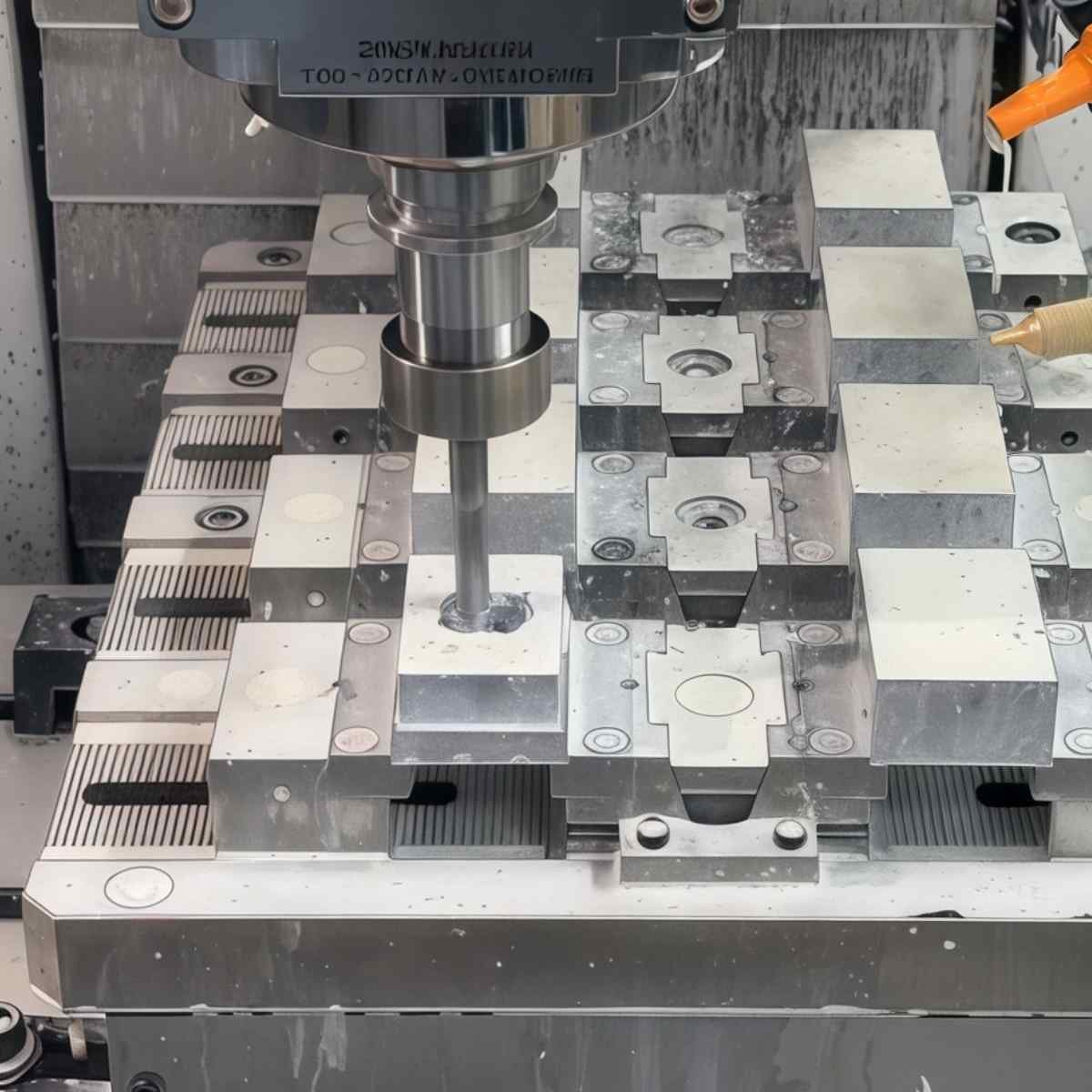
A well-defined fixture tolerance standard also sets the re-certification interval. Production fixtures lose accuracy as locators wear, so the standard should state how often to measure and when to replace. Common practice: re-certify monthly for high-volume fixtures, quarterly for medium runs, and after any crash or repair.
Typical practice: fixture features are held to a fraction of the part tolerance. If the part calls for ±0.1 mm on a critical dimension, the fixture features that control it should be held to ±0.02 to ±0.03 mm. This ratio — roughly 3 to 5 times tighter than the part — keeps fixture error small enough to be absorbed by the process.
The Standard Fixture Tolerance Values
Industry practice has settled on reference values that work for most machining and assembly fixtures. These are starting points, not absolutes — adjust based on part tolerance and process capability.
| Fixture Feature | Standard Tolerance | Tight Precision | Typical Application |
|---|---|---|---|
| Locating pin position | ±0.05 mm | ±0.01-0.02 mm | Machining fixtures, check fixtures |
| Locating pad height | ±0.05 mm | ±0.01-0.02 mm | All fixtures |
| Locating pin diameter | ±0.01 mm (H7) | ±0.005 mm | Precision bores |
| Clamp pad position | ±0.1 mm | ±0.05 mm | Clamping points |
| Datum targets (buttons) | ±0.05 mm | ±0.02 mm | Sheet metal, weld fixtures |
| Bushings (drill jigs) | ±0.01 mm (H7/p6) | ±0.005 mm | Drill and ream jigs |
| V-block centerline | ±0.05 mm | ±0.02 mm | Cylindrical parts |
| Overall fixture base flatness | 0.05 mm | 0.02 mm | Base plates, pallets |
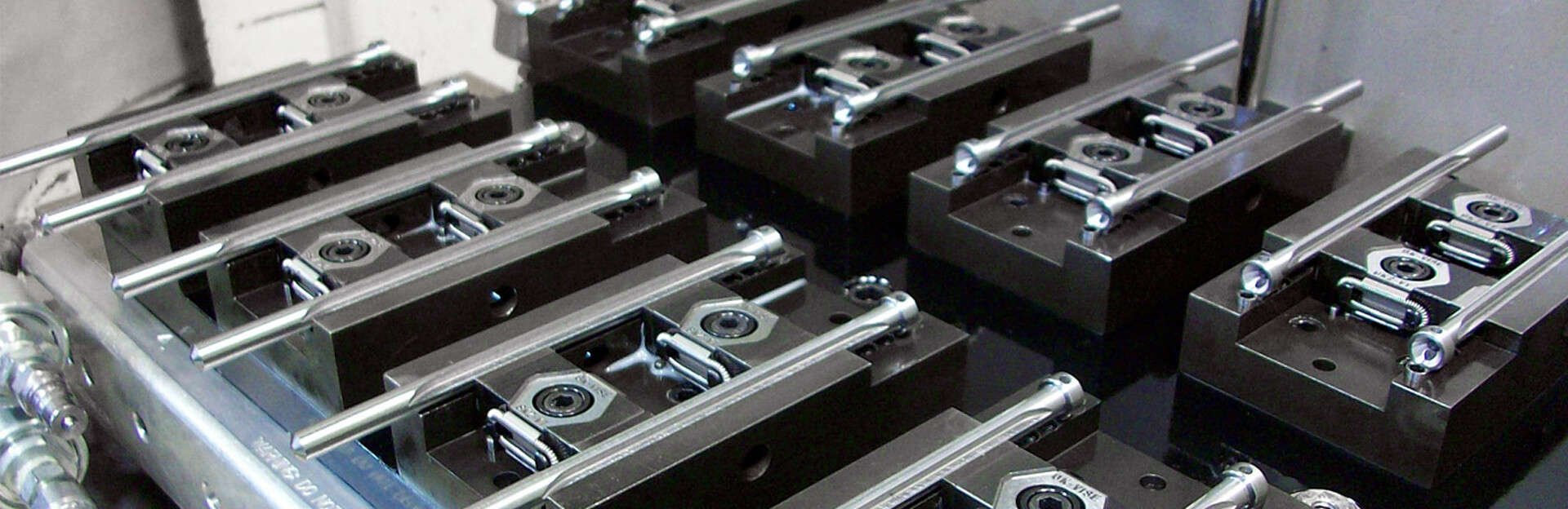
Fixture tolerance values also depend on the fixture material. Aluminum fixtures are cheap to machine but wear and expand faster than steel. Hardened tool steel locators hold tolerance longest but cost more. Composite and cast-iron fixtures sit in between. A good fixture tolerance standard states the default fixture material so designers get consistent, predictable performance. Fixtures sit within the broader assembly tools family — jigs, clamps, and workholders all follow the same accuracy logic.
For most general machining fixtures, ±0.05 mm on locating features is the working standard, and it is a safe default for any new fixture tolerance standard. Automotive check fixtures commonly demand ±0.05 to ±0.1 mm on locators with ±0.1 mm on clamp points. Aerospace and precision mold work goes tighter — down to ±0.01 mm or better on critical features.
Fixture Tolerance vs Part Tolerance
The relationship between fixture tolerance and part tolerance drives every design decision. Understand the 10% rule and the tolerance stack before setting values.
The 10% rule. A common guideline: fixture error should not consume more than about 10% of the total part tolerance band. A part with ±0.1 mm tolerance leaves ±0.02 mm total budget for fixture plus machine error combined. Divide that between fixture features and machine repeatability, and individual fixture features often end up at ±0.005 to ±0.01 mm.
Tolerance stack-up. Part position error comes from the sum of errors — fixture locator position, locator wear, part-to-fixture clearance, and machine positioning. Statistical stacking (root-sum-square) is more realistic than worst-case addition for production fixtures. Design to the RSS value, not the sum.
For parts with generous tolerances — say ±0.5 mm on a weldment — a ±0.1 mm fixture tolerance is entirely adequate. Thermal stability of both part and fixture is managed with temperature control units in processes where heat affects fit. For precision machined components at ±0.02 mm, the fixture needs sub-micron-level care. Match the fixture tolerance standard to the part, not to a universal number.
Check Fixture Tolerance Standards in Automotive
Automotive body and powertrain work has formalized check fixture tolerances through customer standards. These are the most detailed fixture tolerance specifications you will encounter, and they are worth understanding even if you do not work in automotive.
A check fixture (or inspection fixture) verifies that a production part meets its dimensional requirements. Because the fixture itself is the gauge, its tolerance is much tighter than the part tolerance — typically one-tenth or less. OEM standards like Ford, General Motors, and Mercedes define locator tolerances, pin fits, and gauge feature accuracy to the micron range.
General practice in automotive check fixture tolerance:
Locating pins are held to ±0.01 mm on position with H7 fit in the fixture, and gauge pins are replaced as soon as measurable wear appears. Datum target pads are machined to ±0.05 mm height with surface finish Ra 0.4 or better. Gauge features that measure part features are positioned to ±0.01 mm. Clamping elements get looser tolerance, ±0.1 mm, since they only secure the part.
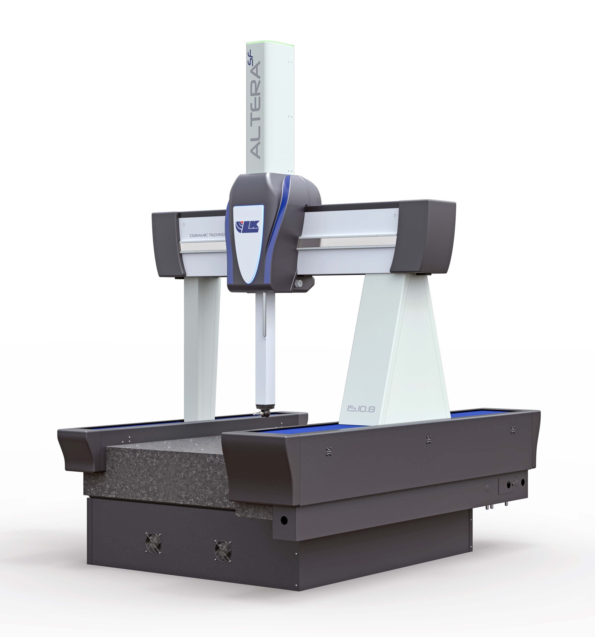
When designing a check fixture, the fixture tolerance standard should be documented on the drawing with a note stating the datum reference frame and the gauge tolerance scheme. This documentation ties directly into quality capability management, where inspection traceability is a formal requirement. This is what makes a fixture audit-able — and what separates a check fixture from a simple holding jig.
Fixture Tolerance for Welding and Assembly
Welding fixtures live in a different tolerance world than machining fixtures. Heat distortion and part spring-back dominate, so the fixture tolerance standard is looser — but still critical.
Typical welding fixture tolerances: locator positions ±0.1 to ±0.2 mm, datum buttons ±0.1 mm, and clamp positions ±0.2 mm. These numbers accommodate thermal expansion and allow the weldment to distort within acceptable limits. Tighter is not always better — a too-rigid welding fixture can lock in stresses that distort the part after unclamping. Welding fixtures also need generous clearance around weld access points and allowance for heat from the weld itself, which can warp thin fixture elements over time. Using thicker section steel for weld fixture bases and keeping critical locators away from high-heat zones extends fixture life and holds tolerance longer.
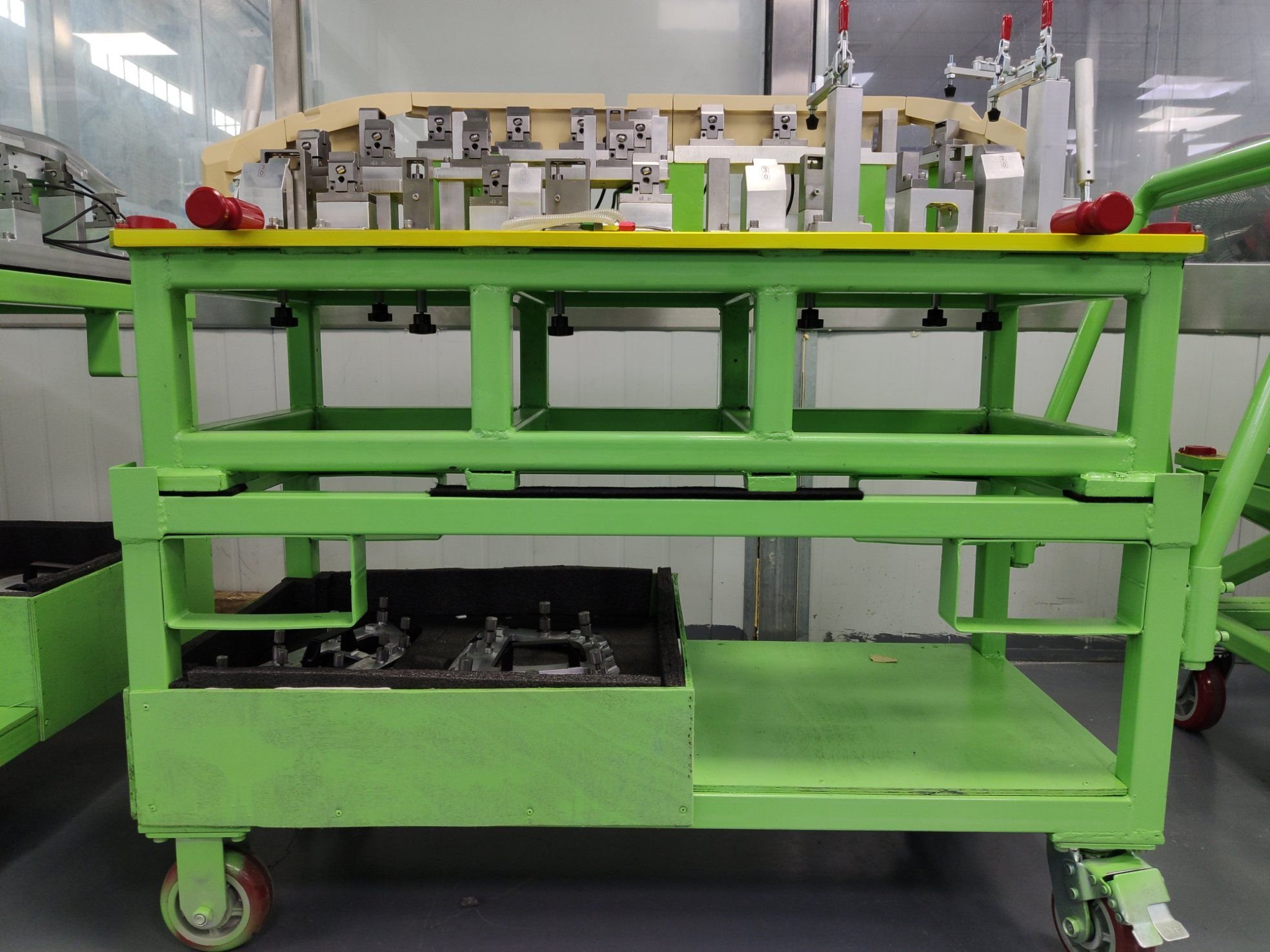
These numbers accommodate thermal expansion and allow the weldment to distort within acceptable limits. Tighter is not always better — a too-rigid welding fixture can lock in stresses that distort the part after unclamping.
Assembly fixtures fall between machining and welding. For parts assembled with fasteners, tolerances of ±0.1 mm on locating features usually work. For precision assemblies like gearboxes or optics, treat the fixture like a machining fixture and tighten accordingly. Detailed design guidance is available from Carr Lane engineering references.
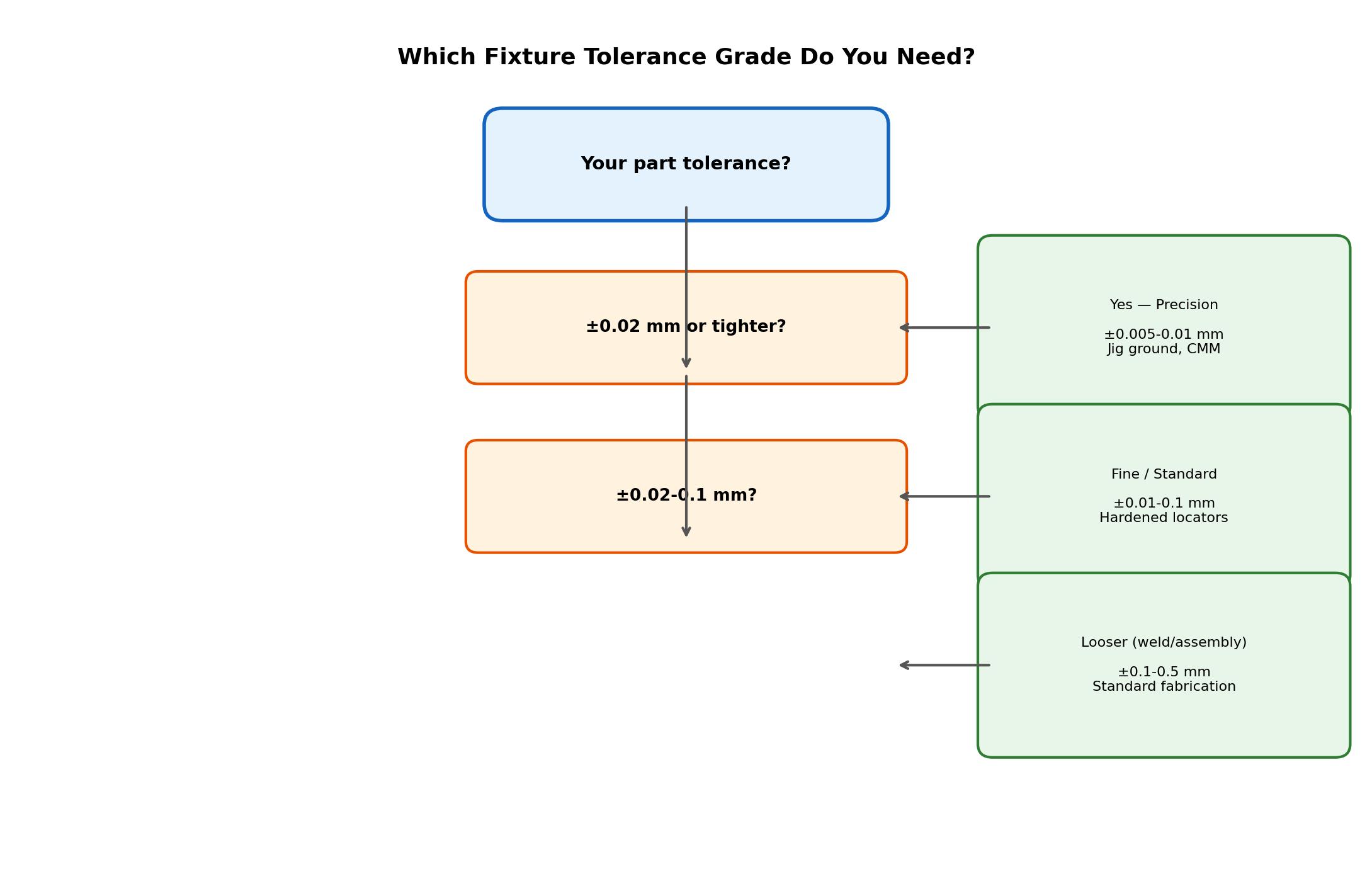
Fixture Tolerance Grades by Application
Different applications justify different fixture tolerance levels. Use this grading as a quick reference when you set your fixture tolerance standard.
| Grade | Locator Tolerance | Typical Industries | Fixture Manufacturing Method |
|---|---|---|---|
| Precision | ±0.005-0.01 mm | Aerospace, optics, medical | Jig grinding, CMM verified |
| Fine | ±0.01-0.05 mm | Automotive, precision machining | CNC machining, hardened locators |
| Standard | ±0.05-0.1 mm | General machining, fabrication | Conventional CNC |
| Assembly | ±0.1-0.2 mm | Welding, sheet metal assembly | Standard fabrication |
| Rough | ±0.2-0.5 mm | Welding (large structures) | Heavy fabrication |
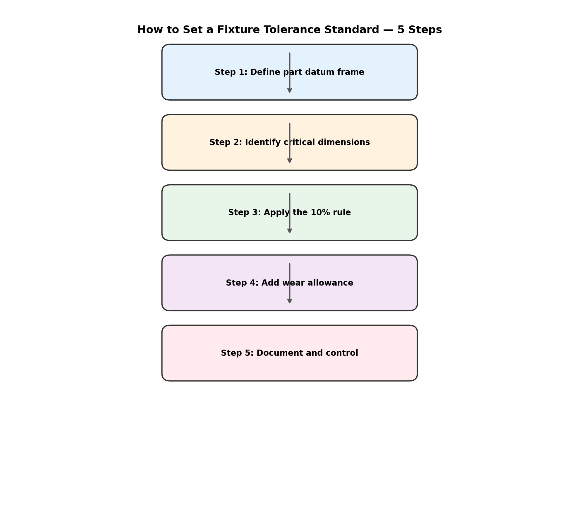
How to Set Your Fixture Tolerance Standard
Follow a structured process instead of guessing values. These five steps produce a defensible fixture tolerance standard for any shop.
Step 1 — Define the part datum reference frame. The fixture must locate the part on the same datums the drawing uses. Mismatched datums guarantee scrap, no matter how tight the fixture tolerance.
Step 2 — Identify critical dimensions. List the part features that must be held to the tightest tolerance. These drive the fixture tolerance for the locators that control them. Non-critical features let you loosen other fixture features and save cost.
Step 3 — Apply the 10% rule. Allocate at most 10% of each critical part tolerance to fixture error. Split that budget between locating features and wear allowance.
Step 4 — Add wear allowance. Locators wear with every loading cycle. Hardened steel pins and pads, plus a wear allowance in the tolerance budget, keep the fixture accurate across its service life. Plan for re-certification at intervals.
Step 5 — Document and control. Put the fixture tolerance standard on the fixture drawing. The discipline mirrors mold base and insert specification, where every critical feature carries a documented tolerance. Include the inspection method — CMM, gauge pins, height gauges — used to verify the fixture. A fixture without a documented tolerance standard is not inspectable and not maintainable.
Common Fixture Tolerance Mistakes
Even experienced shops repeat a few fixture tolerance errors. Knowing them saves expensive rework — and knowing the fixture tolerance standard prevents most of them from the start.
Not verifying fixtures after repair. A fixture that has been welded, straightened, or had a locator replaced is a new fixture dimensionally. Re-certify it against the standard before it returns to production.
Using one standard for everything. A single fixture tolerance standard applied to every job over-specifies simple parts and under-specifies critical ones. Grade the standard by application and apply the right level.
Over-tolerancing the fixture. Specifying ±0.01 mm on every feature when the part only needs ±0.2 mm drives cost up for no benefit. Tighten only the features that control critical dimensions.
Ignoring wear. A new fixture at ±0.02 mm still passes after 100,000 cycles — or fails — depending on whether hardened locators and wear allowance were designed in from the start.
Undefined datums. A fixture with tight tolerances but no datum reference frame is almost useless, because no one can verify it against the part drawing.
Fixture tolerance tighter than the machine can hold. Specifying ±0.005 mm on a feature that requires a jig borer or CMM to make and inspect, then producing it on a manual mill, guarantees failure. Match fixture manufacturing capability to the tolerance.
Frequently Asked Questions
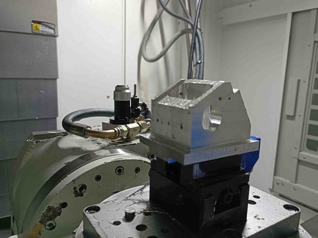
Choosing the right fixture tolerance standard is a cost-versus-accuracy trade. Every micron of tightening raises fixture manufacturing cost, sometimes sharply — a ±0.01 mm feature may need grinding or jig boring instead of standard milling. The discipline is to tighten only what the part requires.
What is a standard fixture tolerance?
For general machining fixtures, ±0.05 mm on locating features is the common standard. Check fixtures for automotive use ±0.01 to ±0.05 mm. Welding fixtures run looser at ±0.1 to ±0.2 mm. The right value depends on the part tolerance and process capability.
What is the 10% rule for fixture tolerance?
The 10% rule says fixture error should consume no more than about 10% of the part tolerance band. A part at ±0.1 mm leaves roughly ±0.02 mm for combined fixture and machine error, so individual fixture features end up tighter still.
How tight should a check fixture be?
Check fixtures are gauges, so they are held much tighter than the parts they check — typically one-tenth of the part tolerance. Locating pins at ±0.01 mm and gauge features at ±0.01 mm are common automotive check fixture standards.
Do welding fixtures need tight tolerances?
No — welding fixtures typically run at ±0.1 to ±0.2 mm on locators. Heat distortion and spring-back dominate, so over-tightening a welding fixture can create more problems than it solves. The standard balances dimensional control with thermal reality.
Who sets the fixture tolerance standard?
Standards come from three places: the customer (OEM standards like Ford or GM for check fixtures), the industry (aerospace and automotive published guides), or your own shop. Most shops write an internal fixture tolerance standard that references customer requirements where applicable. The best fixture tolerance standard is the one that is written down, verified, and enforced.
How do I verify my fixture is still in tolerance?
Regularly re-certify fixtures using the inspection method defined on the drawing — typically CMM measurement of locator positions or gauge pin checks. Compare against the documented fixture tolerance standard and rebuild or replace worn features before they push parts out of tolerance.
What is the fixture tolerance standard for CNC milling fixtures?
For general CNC milling fixtures, ±0.05 mm on locating features is a solid fixture tolerance standard. If the part has critical features at ±0.02 mm or tighter, tighten the controlling locators to ±0.01 mm and consider hardened, replaceable locators. The fixture tolerance standard should always be defined relative to the tightest part tolerance it controls.
What is a datum target on a fixture?
A datum target is a small, defined surface on the fixture (often a button or pad) that contacts the part at a specified point. Datum targets replace full-surface contact, giving predictable, repeatable location. They are standard on sheet metal and weld fixtures, and their tolerance is usually ±0.05 to ±0.1 mm.
Conclusion
The fixture tolerance standard is the foundation of repeatable machining. A fixture tolerance standard that is documented, applied, and re-certified removes the most common source of dimensional scrap — the fixture itself. Every hour spent setting the right fixture tolerance standard pays back across every part the fixture ever holds. Match fixture feature tolerances to part requirements with the 10% rule, apply wear allowance, document datums, and re-certify on schedule. A fixture designed to a clear tolerance standard produces consistent parts from the first run to the last.
Fixture accuracy also depends on how the workpiece and fixture behave under temperature — thermal growth shifts locator positions and part dimensions alike. Temperature-controlled processes keep thermal drift predictable, and quality capability checks catch drift before it becomes scrap.